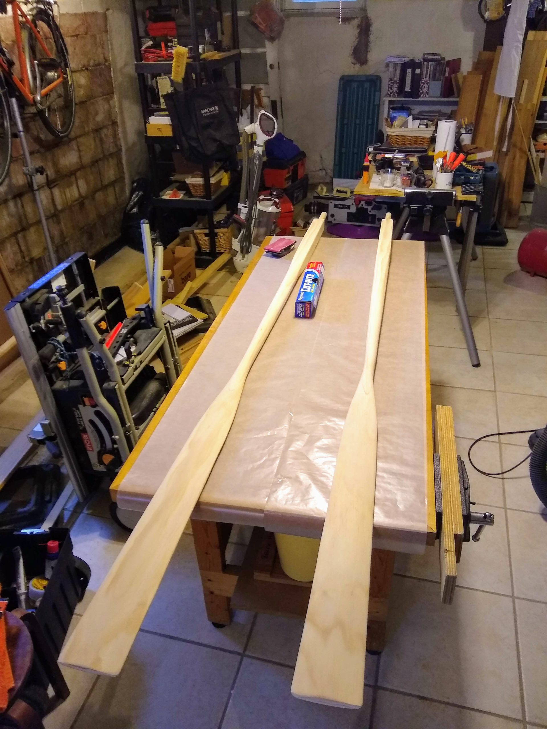
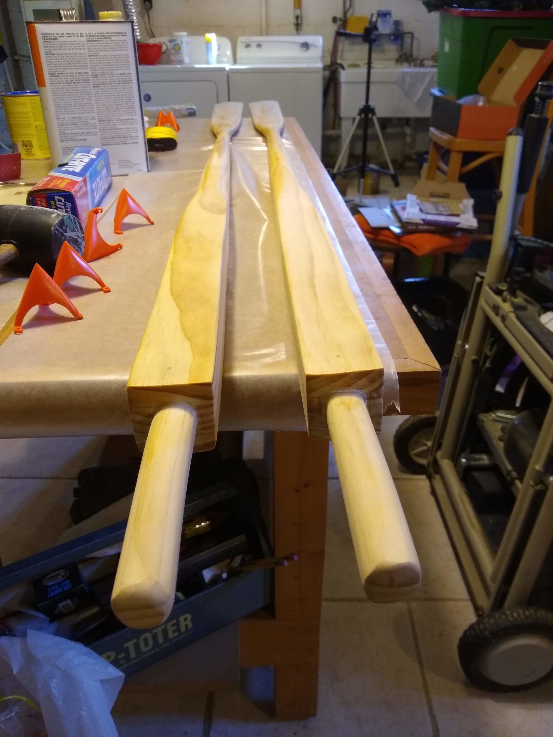
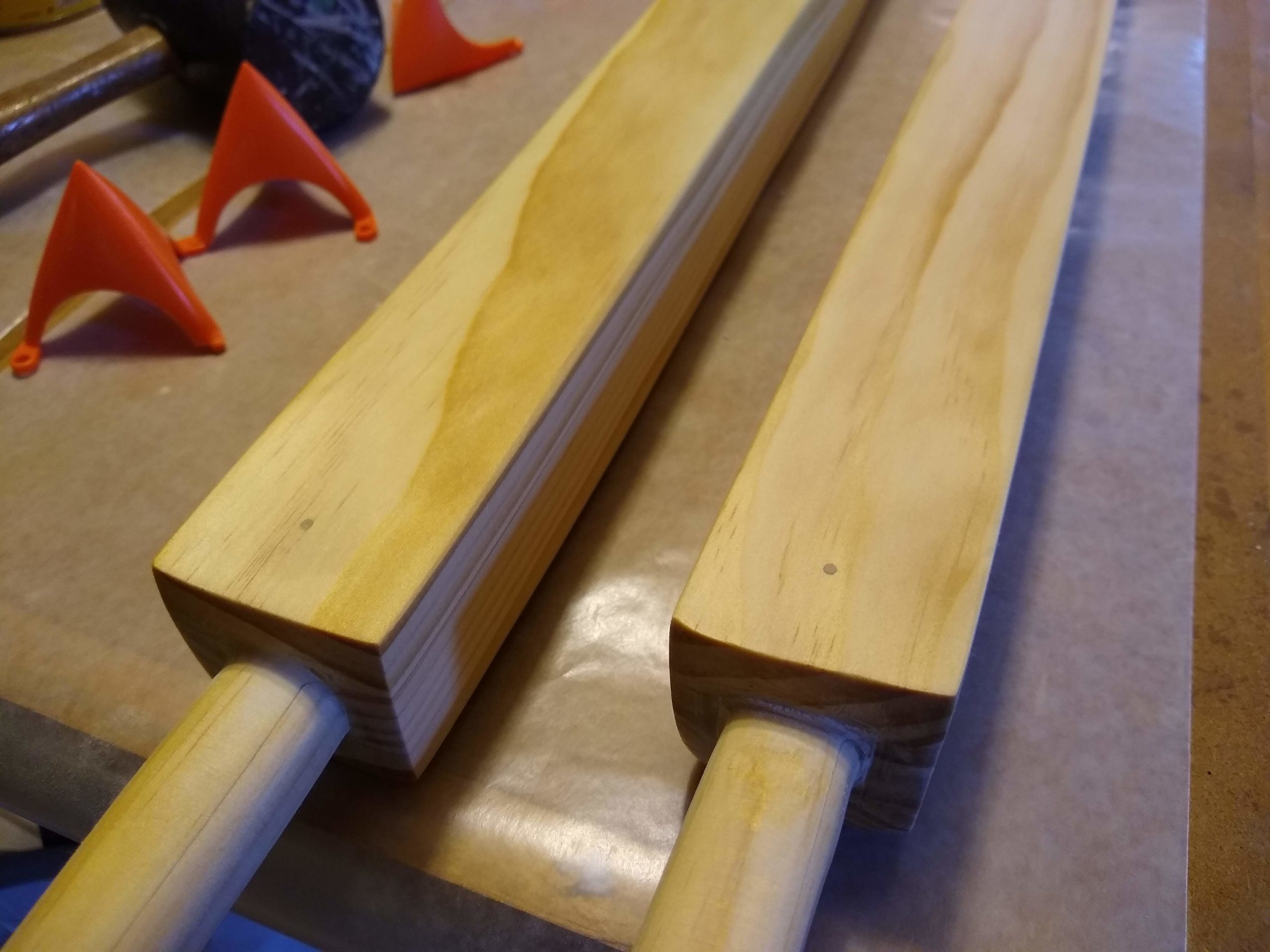
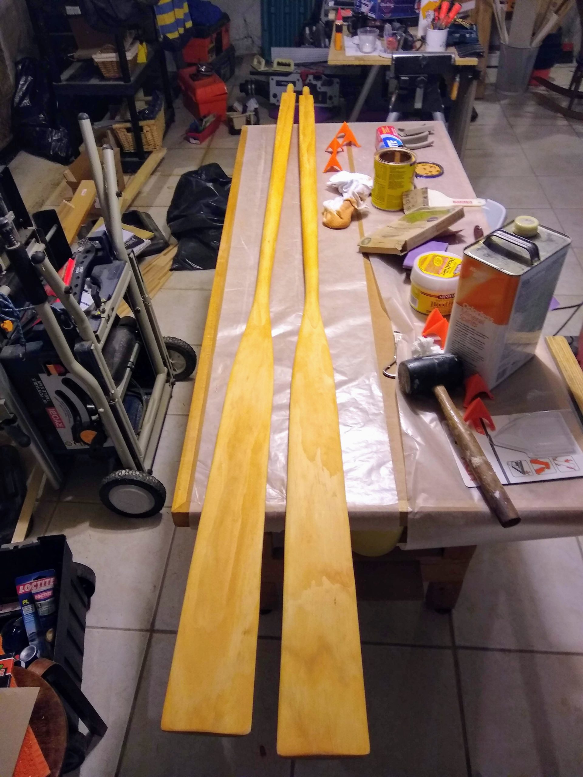
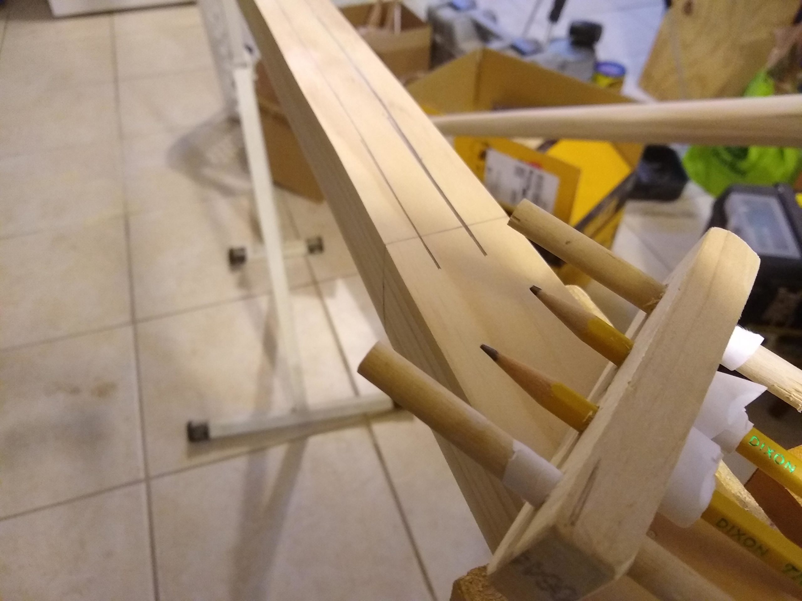
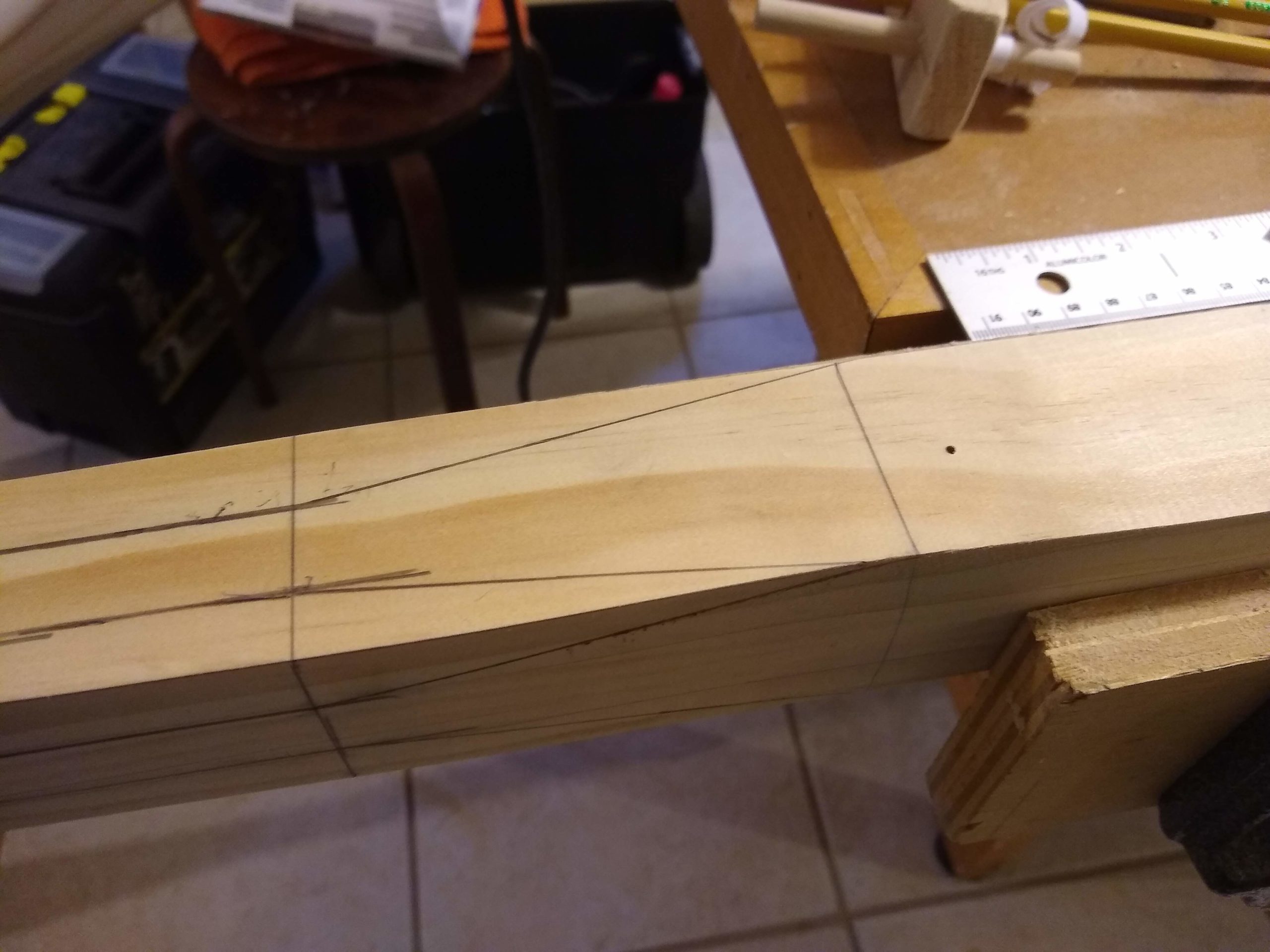
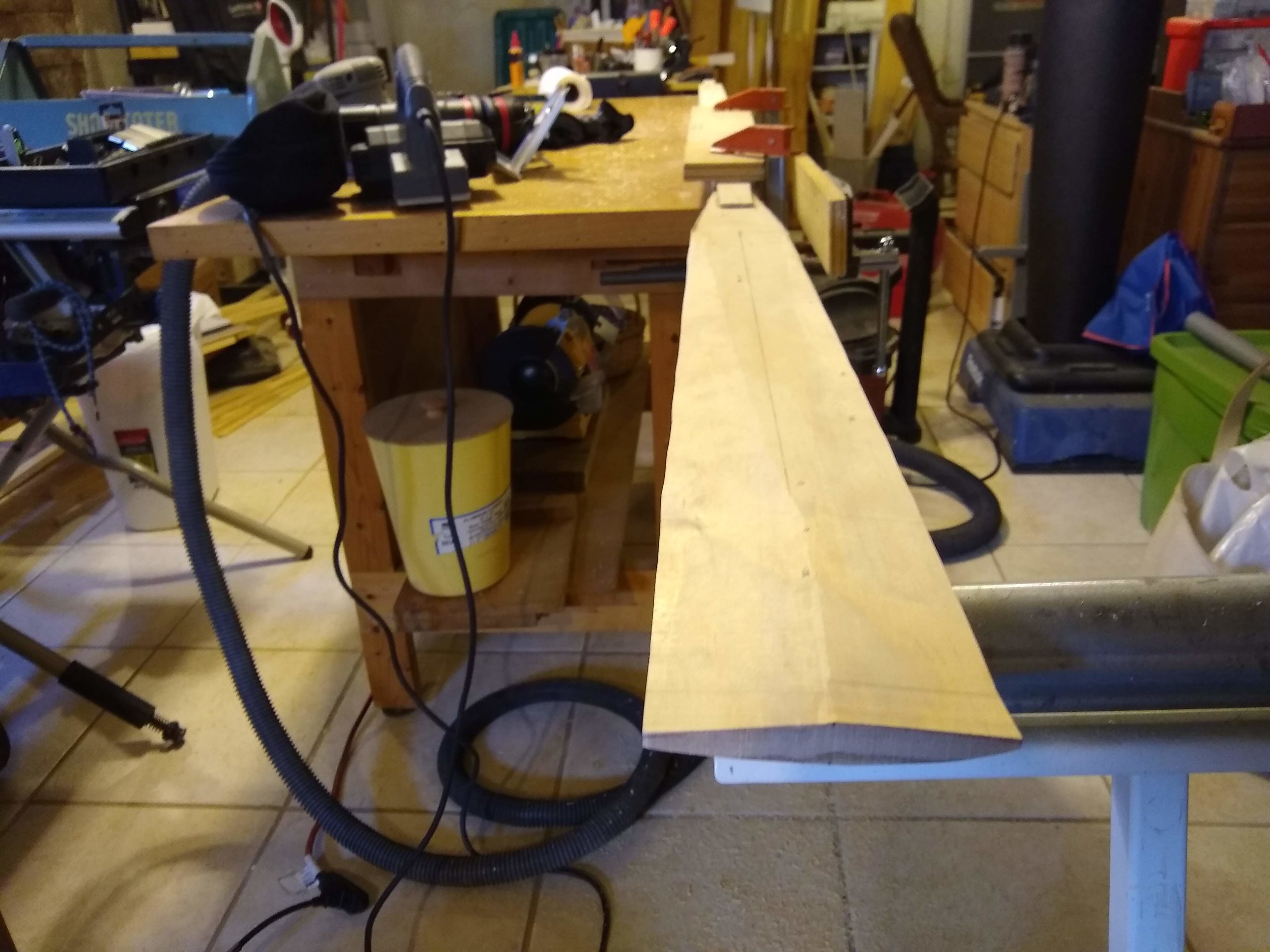
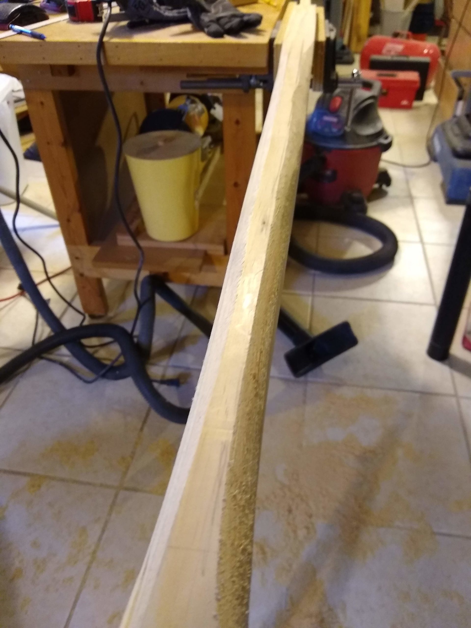
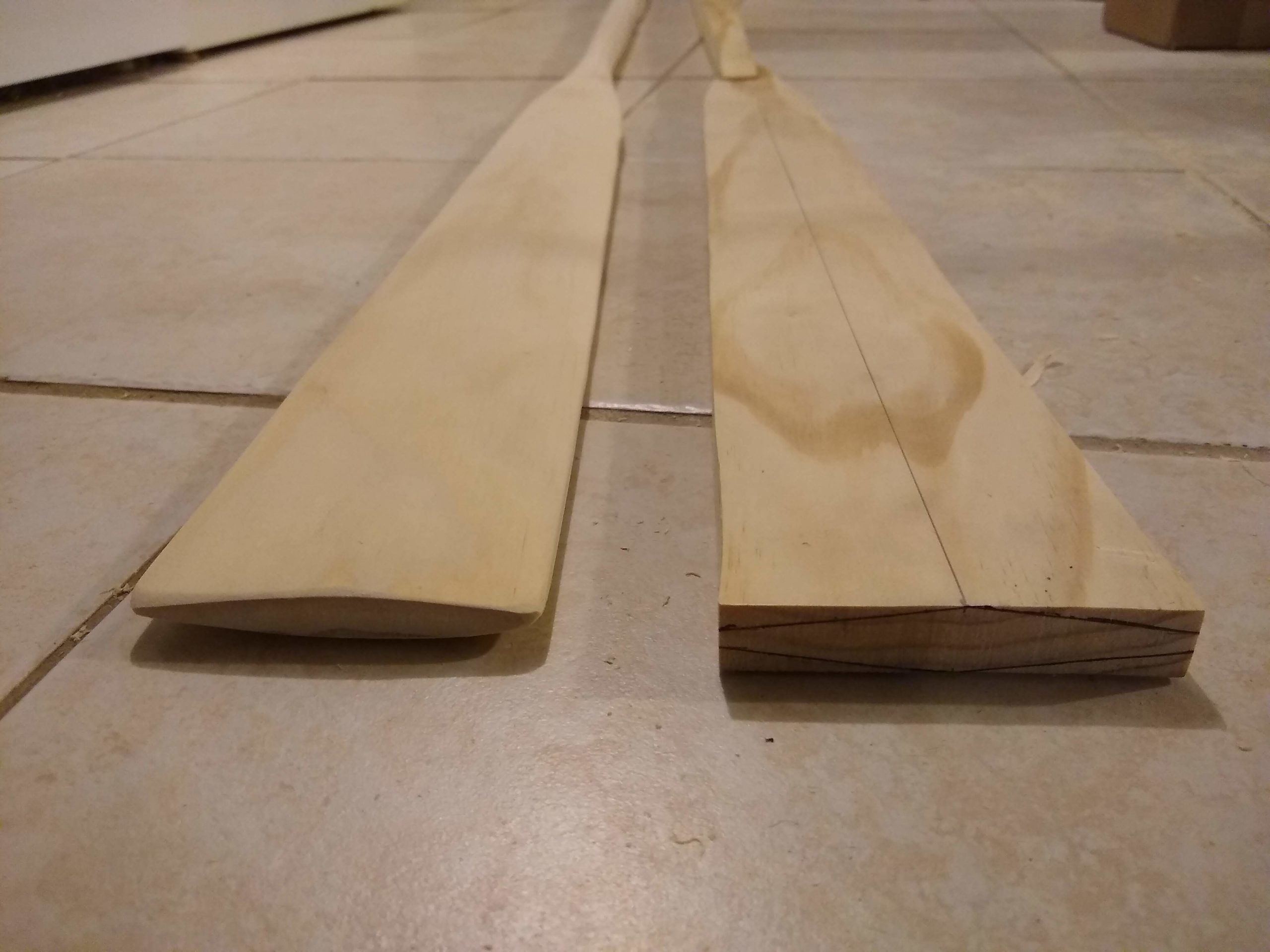
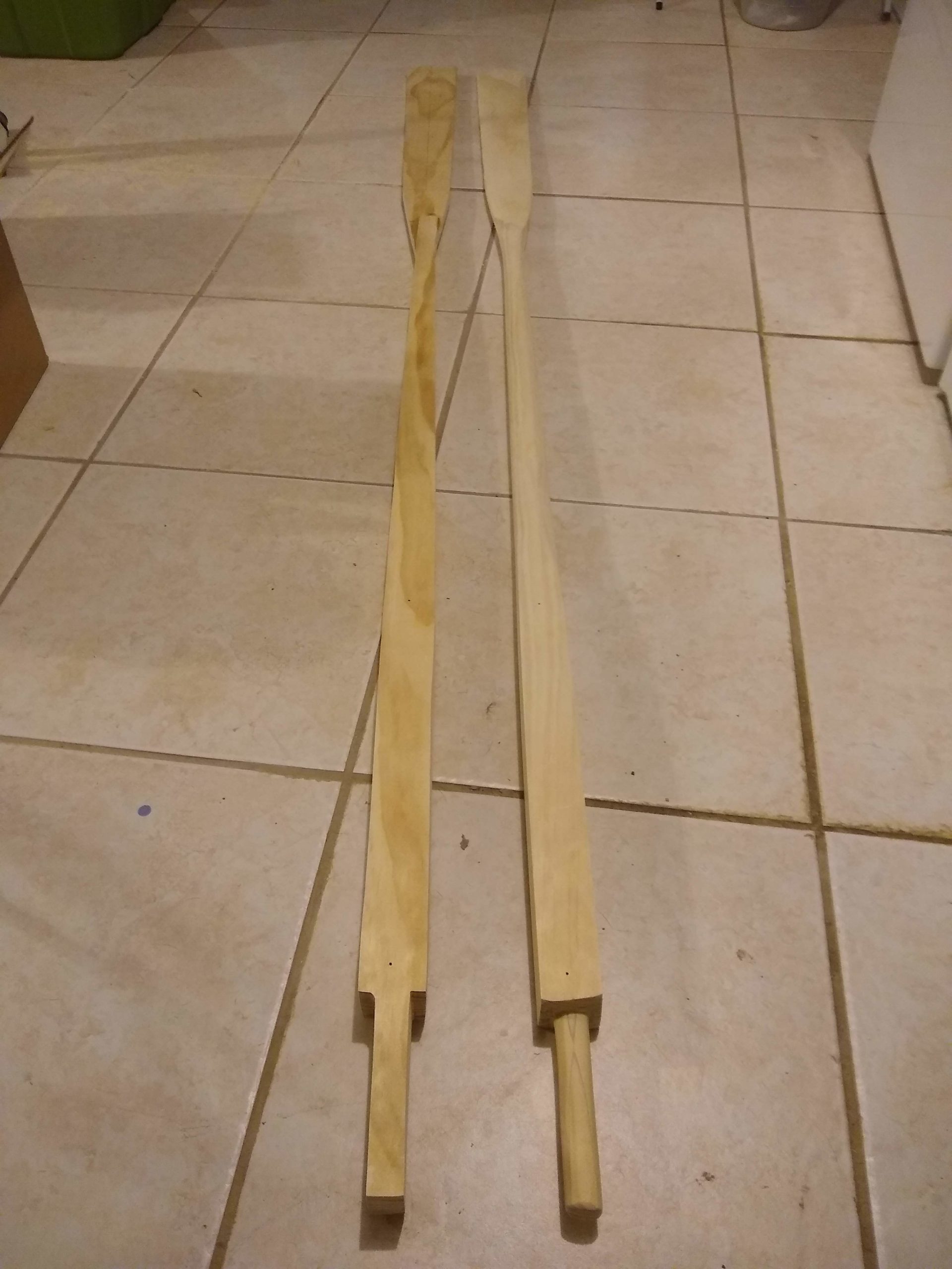
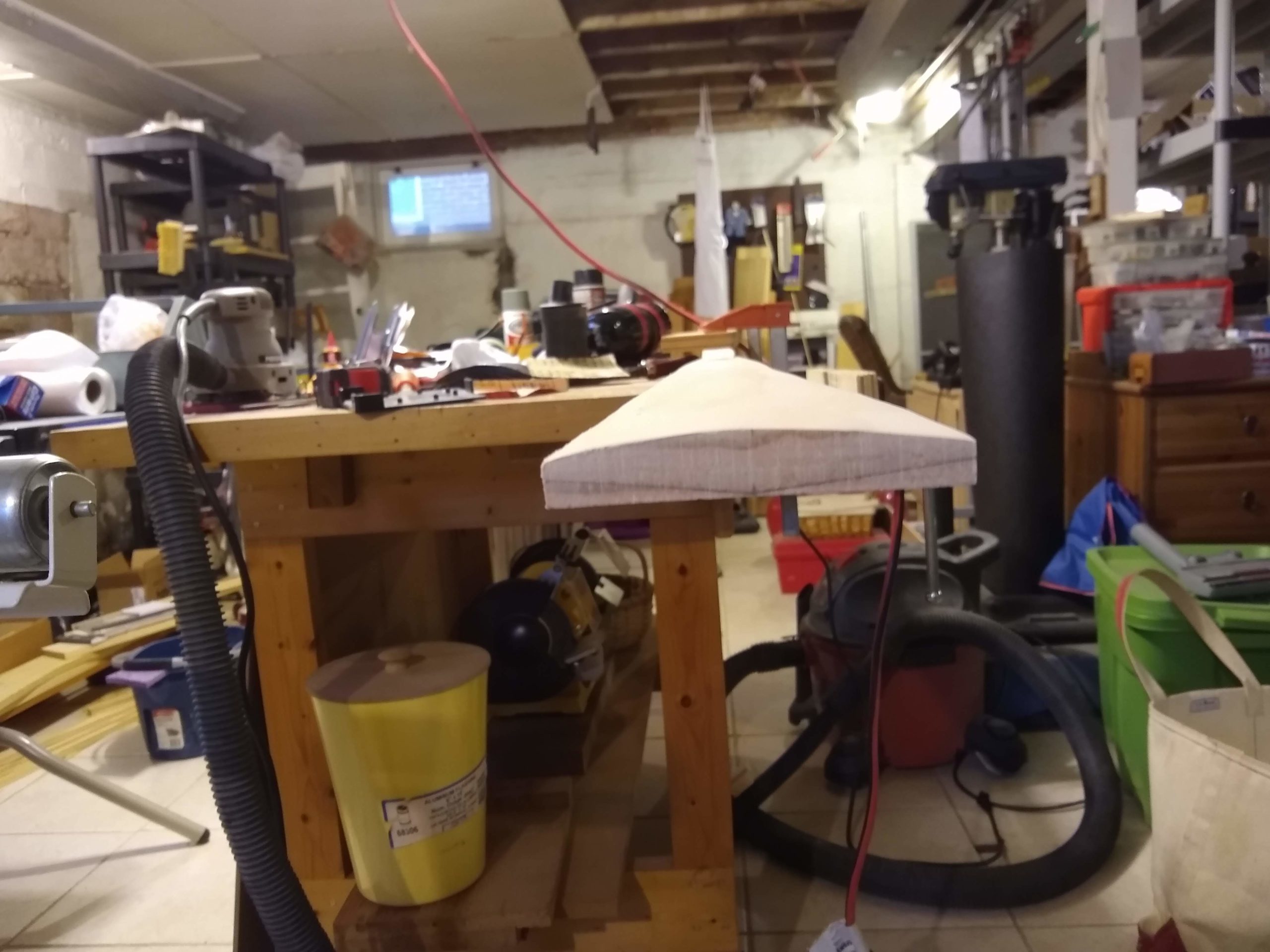
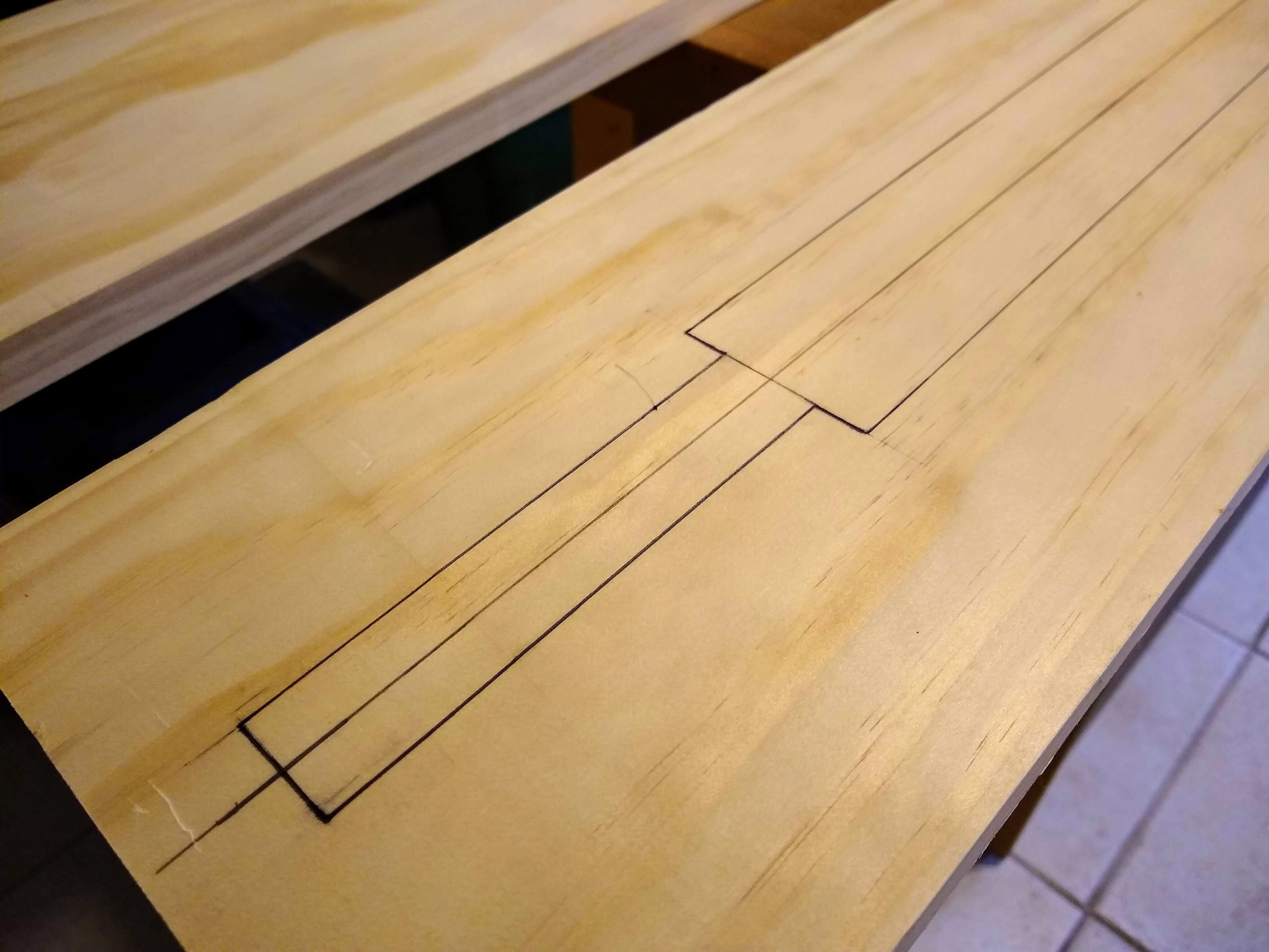
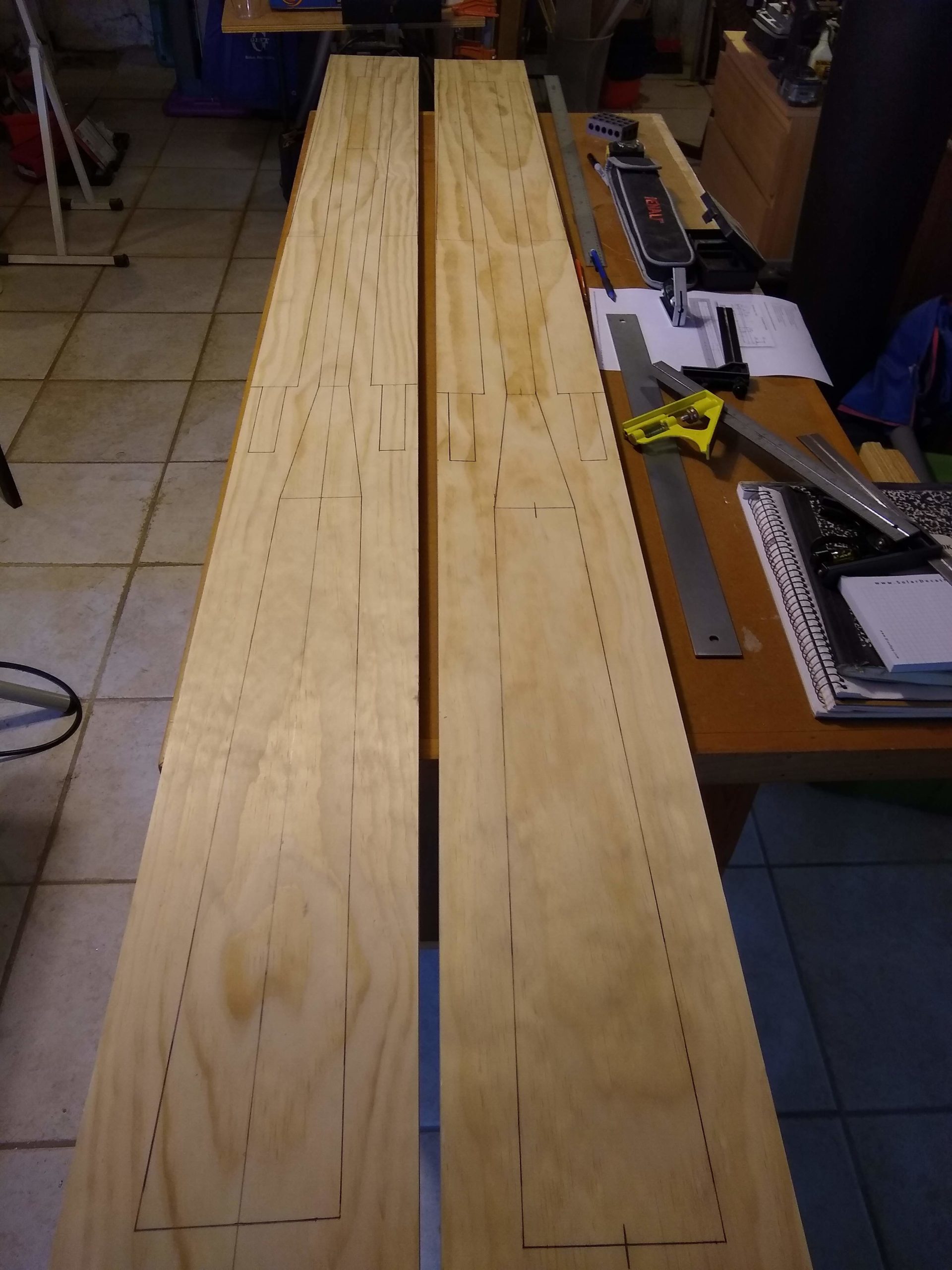
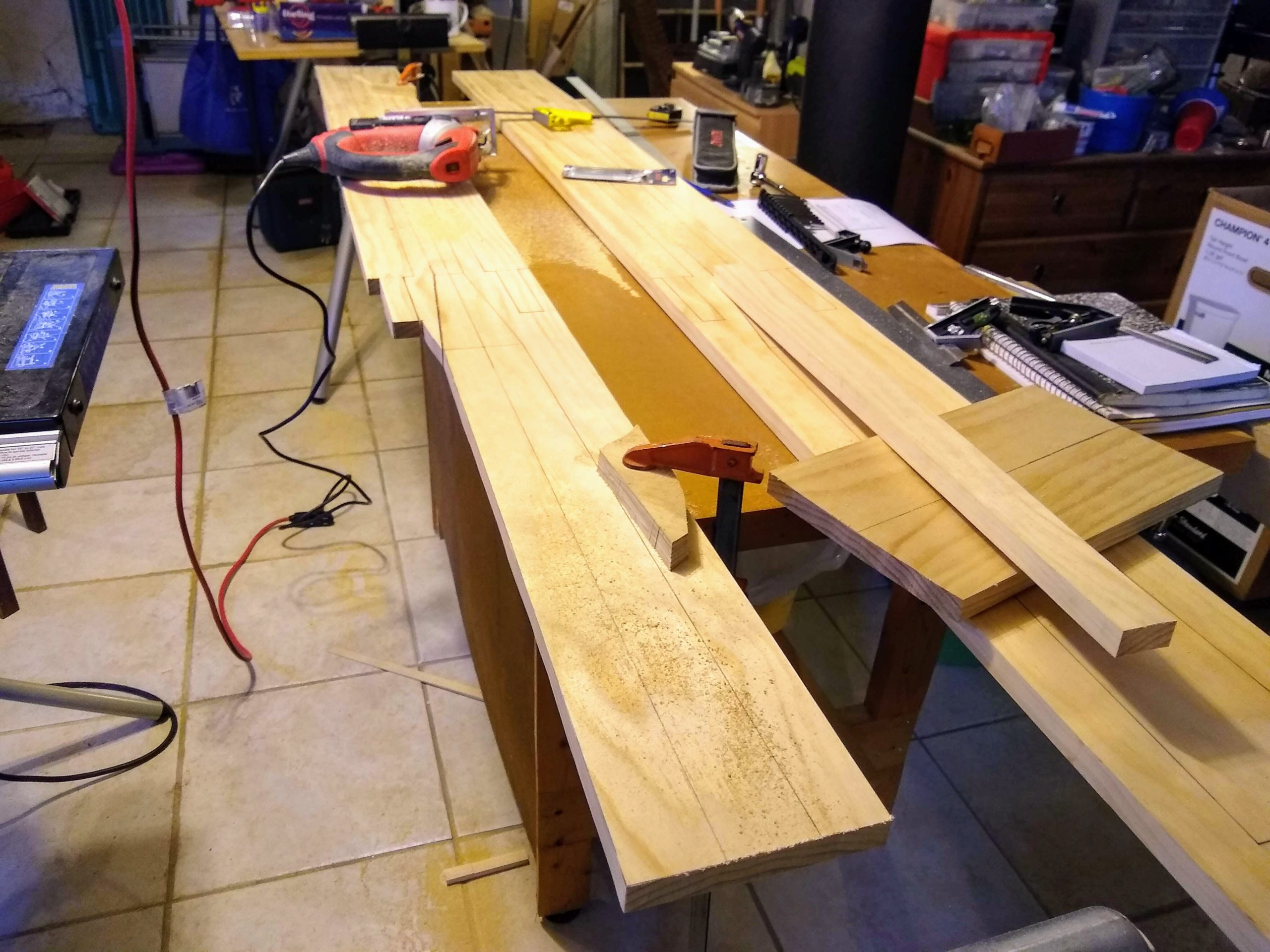
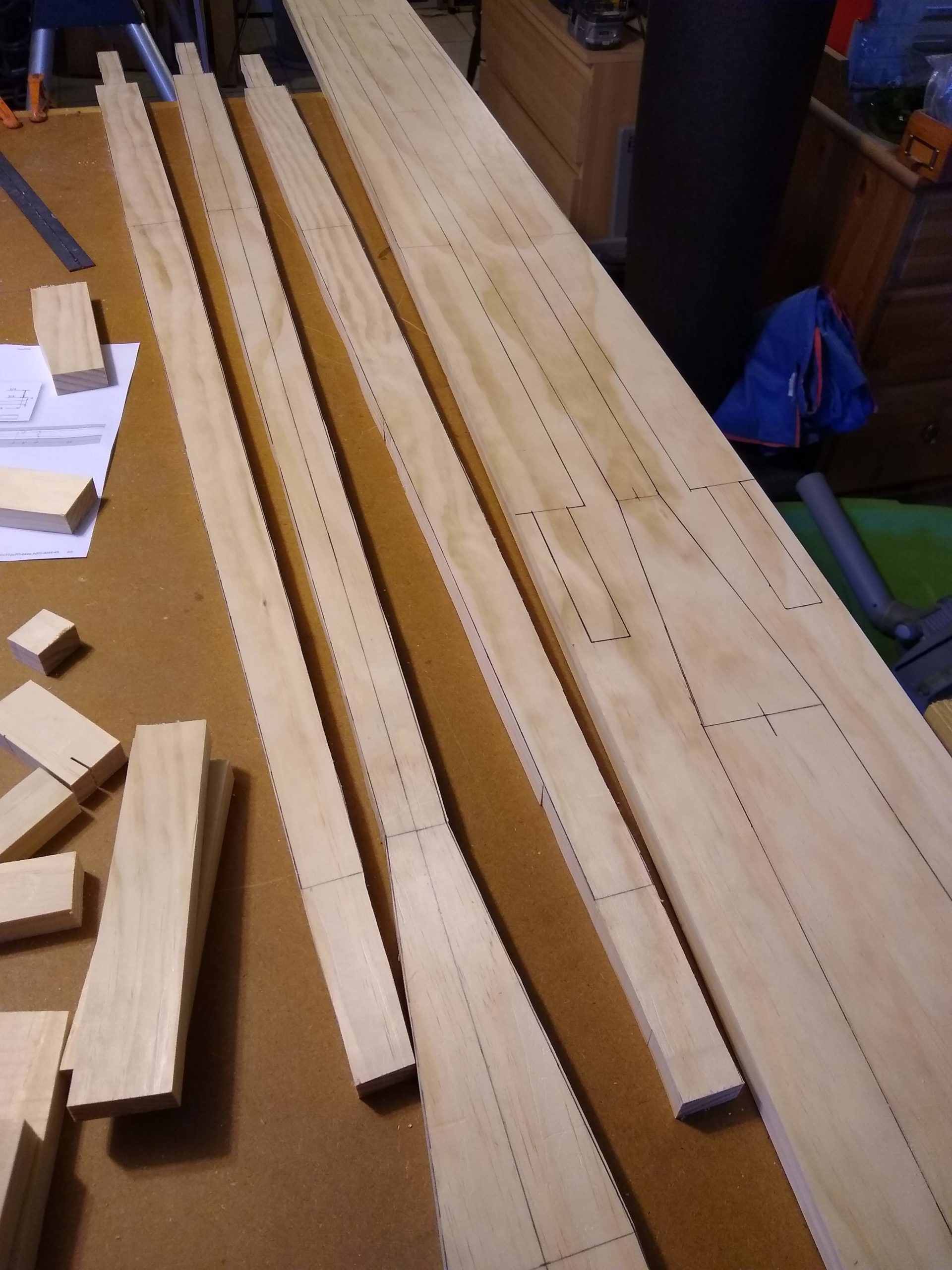
Shaped the second oar, pretty much just like the first. Except that I learned maybe a thing or two from the first oar that I was able to do better on the second oar.
Gadget and layout lines
One was being a little more careful with the gadget in drawing the lines. The pencils have a tendency to drift toward each other if they’re not held rigidly when drawing the lines. Not a big deal, in that they’re just making layout lines and not actually cutting anything, but it just feels better to look at them when they’re straighter.
Square to round transition lines
More important, though, was cutting the handle to square before shaping it round. I used the dozuki saw instead of the ryoba, and I made relief cuts into the waste area so that I could readjust to a straighter cut if I got off track. It was much better.
So now I’ve got both oars shaped. Next up is staining and varnishing.
Working Saturday and Sunday, as well as on Monday night, I finished shaping one of the two oars.
I used the electric planer to remove as much stock on the second side of the blade as I could before finishing with the rasp. I tried a few different methods with the planer, trying to say exactly on one side of the blade, using the fence that came with the planer as well as attempting to use a metal ruler as a fence. Neither worked very well; in fact, I cut some of the ruler as it was way too thin to be an effective fence. Luckily it’s aluminum, I think, and didn’t damage the planer knives.
Both sides of oar being shaped
I made a little gadget that Jim Michalak suggests using to mark out the layout lines when turning the 4-sided looms into 8 sides, on their way to being round. I thought I had measured the holes well enough to hold the pencils and the dowels that I’m using as little fences, but the holes turned out to be a bit big. So I shimmed them as best I could by wrapping paper around the dowels and pencils. It worked, meh, just okay. If I were building oars for a living I’d make a better version, maybe epoxy for the dowels and little wedges for the pencils.
Gadget
Jim Michalak says that he leaves his looms (and handles) 8-sided, rather than shaping them any further. I had originally planned to do the same. But at some point I started rasping the corners of the eight sides a bit, just to soften them, and then I kept going and ending up fully rounding them. And they turned out so utterly wonderfully beyond anything I could have expected. They really look great.
Rasping the loom
But fully rounding the looms did then present me with the problem of how to transition between the square and round parts of the loom. I arbitrarily picked a spot 4 inches down the loom from the end of the square part and from there pretty much split the difference between the points of the octagonal shaping and the points of the squares. That also turned out so much better than I could have imagined.
Square part of the loom, round part too, and a nice transition between them
There’s something of a transition between the bottom of the loom and the top of the blade, and there I used a chisel to pare away the loom stock. That worked out really well, making it a lovely transition.
One oar shaped, one not yet, loom detail
For the handle, I first had to trim the 1″ wide by 2-1/4″ tall handle area to a 1″ square, creating two more shoulders between the handle and the square loom. I used the rip teeth of the double-sided ryoba saw along the 5″ length, and I didn’t cut nearly as straight as I would have wished. So the handle at the shoulder is maybe a little thin. It’s not so bad that bad, though. Maybe you can’t see it. But I sure can see it.
Handle detail
Then I shaped the handle to eight sides and then round, except that I more eyeballed the lines to mark the eight sides rather than use the gadget. And I had to do rather quite a bit of chiseling at the shoulders of the square loom, but they do look a lot better now for it.
So, yeah, wow, the oars have turned out to be harder than I imagined. Who knew?
I knew that I could really benefit from using a hand plane or two for shaping at some point, so I trotted out my antique Stanley #4 smoother and block plain (and my not so antique Buck Brothers jack plane) to try my hand yet again at hand planes. I’ve never been successful with them.
Which is why they’ve been in storage for so long, and also because they suffered terribly in the flood we had in the basement. Oh, my, was there rust. A lot of rust.
And I felt terrible about that. Not that I was any good with these tools in the first place, but, at the very least, I should have been a better steward for the antique Stanley planes. Especially the #4 smoother. It’s a type 15, I’ve learned, made between 1931 & 1932. I feel like I should take better care of it.
So, more recently though, I watched Rex Krueger’s awesome video on restoring old Stanley bench planes. He showed some awesome results with a bench grinder and a wire wheel. And Dawn had just done the taxes and said I had a few dollars to spend on something for myself. So I bought myself the DeWalt DW756.
And it really, really did some good on my #4, getting rid of the heartbreaking rust. I was stunned. But then came trying to sharpen the iron itself. I tried the sandpaper method. I used my oil stones. I used my diamond stones. And I’m still terrible at sharpening.
But, I thought, maybe it’s sharp enough. Maybe I’m not getting a perfect flat mirror lapping the back of the iron, but maybe it’ll cut okay anyway. I’m not trying to get a shimmery surface on tiger maple or anything. I’m just trying to shape some pine.
So I tried using the plane on the taper on the loom on the oar where it goes from the 2″ square down to the 1-1/4″ where it meets the blade. And just a couple of strokes with the plane … and I broke it.
I broke my precious antique Stanley #4.
Now, I only broke the tote, the wooden rear handle, and not the precious cast iron or anything. It’s not the end of the world. But it’s pretty much the end of my career with hand planes.
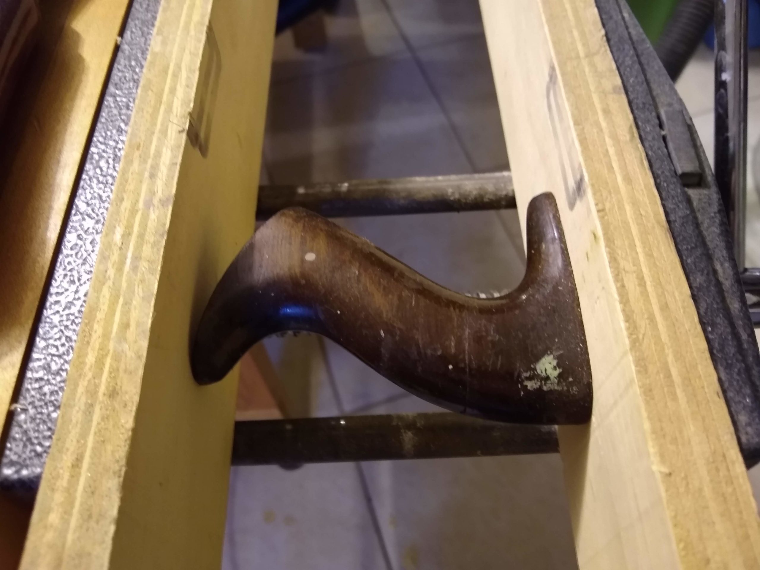
I tried gluing the tote back together with wood glue, but the orientation of the grain makes it pretty much end grain that I’m trying to glue together. It didn’t work. So I used epoxy instead. That made an utterly ugly glue line, but it holds.
Tote being glued
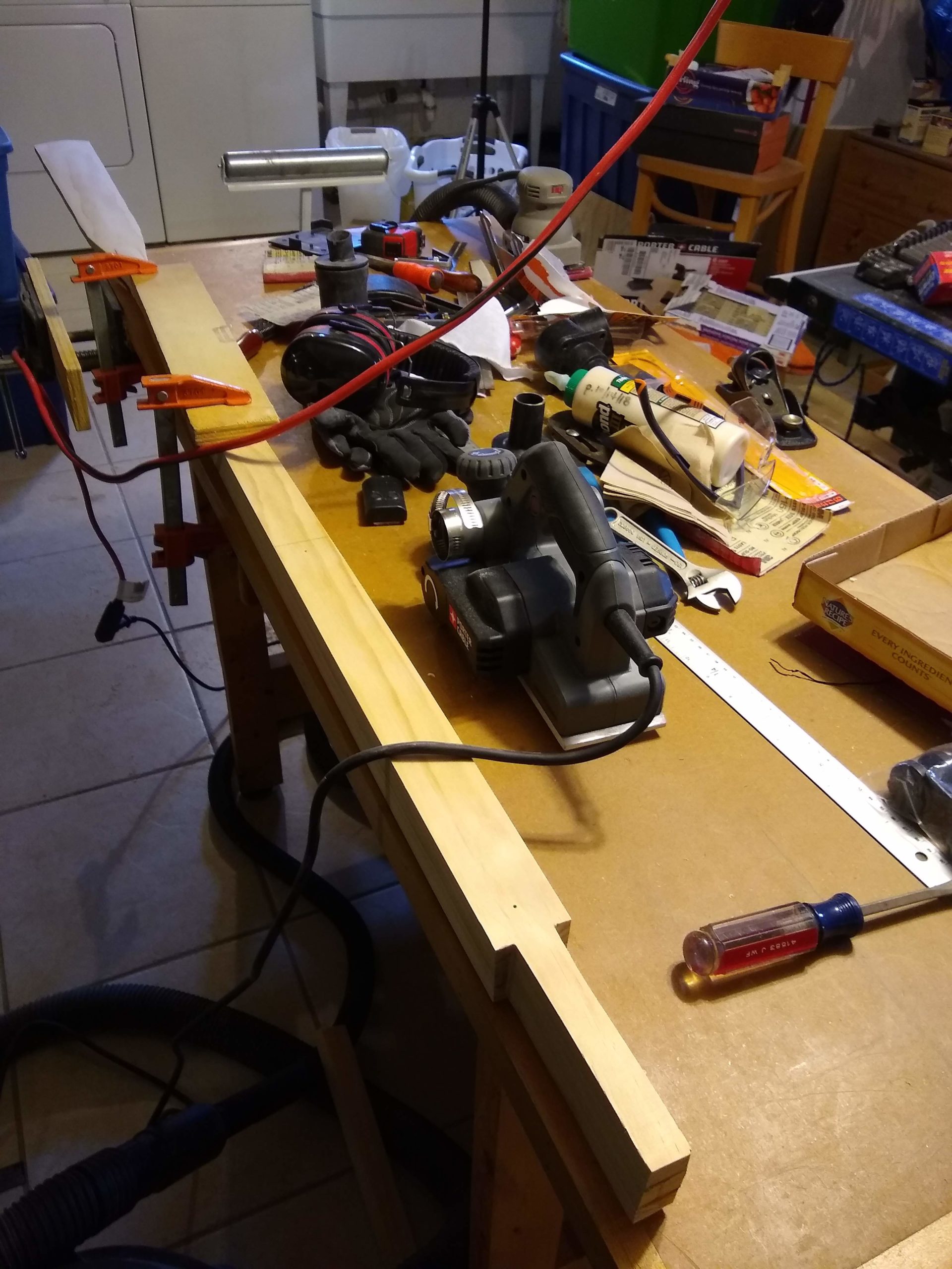
And I instead bought a power hand planer, the Porter Cable PC60THP, which is a malevolent looking beast but works, I suppose. And I used that this weekend to start shaping the oars to their final dimensions.
And it works really well on the square part of the loom, it works less well on the taper part of the loom, and it works surprisingly poorly on the blade. I really thought it would work super well on the blade.
Oar loom shaping with power planer
So I’m back to using the rasp on the blade, which is a good workout. So far I’ve done one side of one blade. A couple more hours of that, though, and I should finish with the oars.
Oar blade shaping with rasp
Oh, and I did get the boat turned right side up, ready for painting the inside yellow. I’ve ordered that paint.
Spent Saturday sizing and shaping oar pieces somewhat, and then glued them up on Sunday.
Each oar is made from three pieces which get glued together in a sandwich, as it were. Once glued, the middle of the sandwich doesn’t get shaped much top and bottom, except for the blade, which isn’t technically part of the sandwich anyway.
But the top and bottom parts of the sandwich, the top and bottom bun, say, while already cut side to side to taper from 2″ square down to 1-1/4″ round, are still 3/4″ thick for their full length. They each need to be 5/8″ thick at most and taper down to only 1/4″ thick at the point where the blade begins. The plans call for removing that extra stock after gluing together, but I’m shaping that some before gluing.
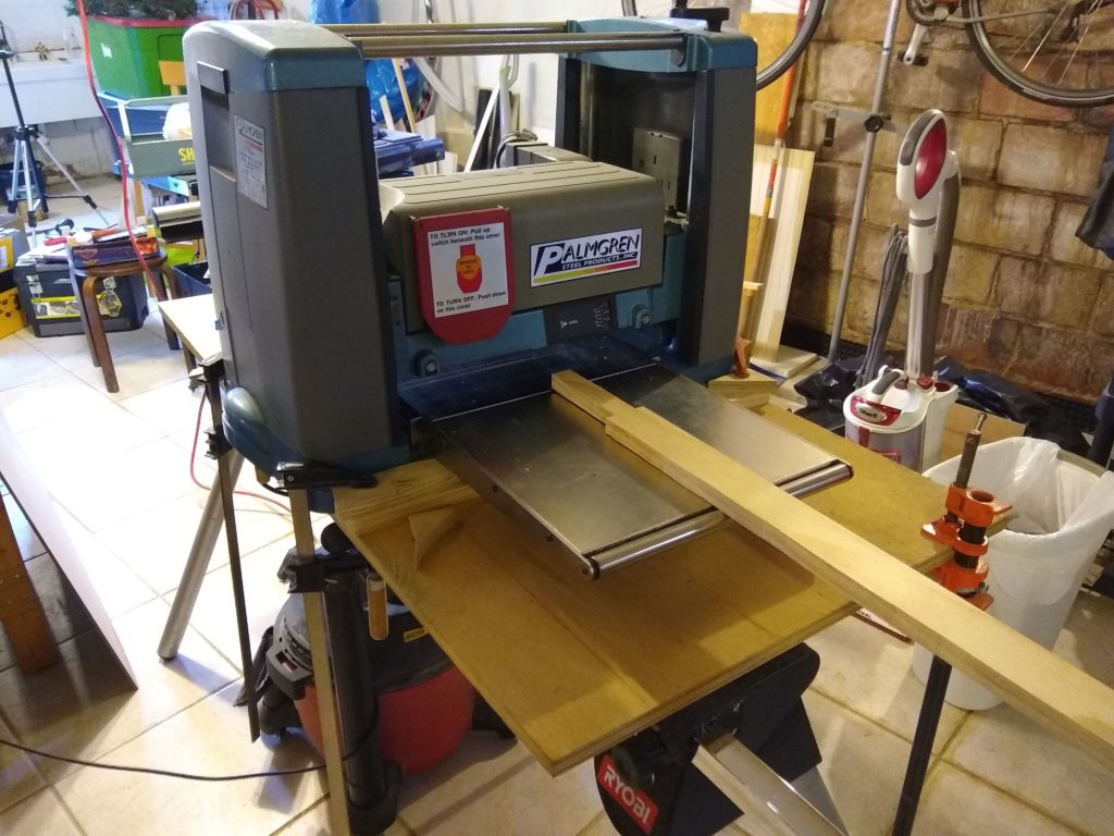
Planer for planing
It’s stupid simple in a thickness planer to take a board 3/4″ thick and make it 5/8″ thick instead. And since I’ve got a planer, that’s what I do. I just make a little mark somewhere for 5/8″ thickness on each part and send them through the planer a few times until they’re down to the mark.
5/8″ thickness is the goal.
The taper from 5/8″ down to 1/4″, though, is a rather more tricky thing. I make some plans for a planer sled, where I would need to raise the bottom end of the bun up 3/8″ so as to plane it down to 1/4″. But I finally decide that a sled is more complicated than this operation needs to be, and besides I don’t think I can make any sort of wedge that’s 30″ long but only 3/8″ high to support the bun under the rollers in the planer. So that board is going to bend and not get planed right. Forget it.
Planed to 5/8″
I consider some sort of taper jig for the table saw, but that leaves a lot of material hanging off the front end of my tiny little table. I’m not comfortable with that, either.
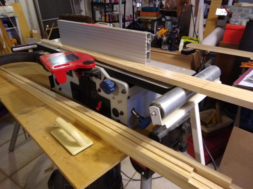
Jointer for jointing
I finally opt for using my little bench top jointer. I have an adjustable roller stand that I butt up against the infeed table, so that the incoming piece being jointed is lifted up … somewhat. Instead of measuring precisely how high above the table it is, I just sight along the jointer fence, trying to keep the line on the board level with the horizontal fluting along the fence.
This works, turns out. Works just fine, especially since I’m only aiming for getting close to the final line rather than exactly on it. I’m only removing most of the stock, not all of it. I’ll still be doing some final shaping after gluing the sandwiches together, with plane and/or rasp and/or file and/or sandpaper.
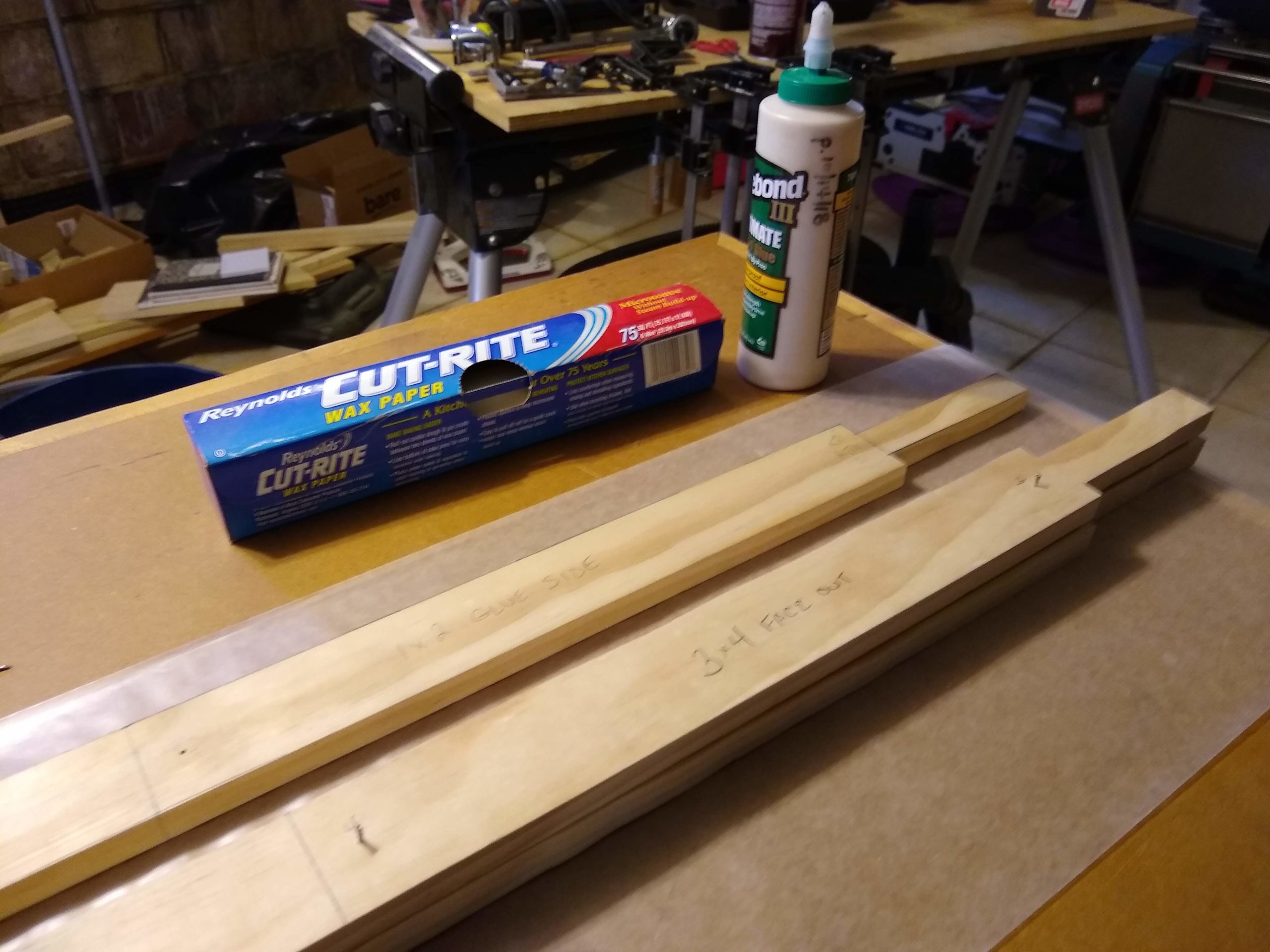
Gluing set up
Gluing the sandwiches together is fairly straightforward, except that I worry about the parts sliding around with the slippery glue while I’m trying to clamp it all together. Jim Michalak suggests tapping in a “light temporary nail to keep the pieces from sliding around on each other because almost all glues are quite slippery until they start to set.” Ain’t it the truth.
Glue sides and show side clearly labeled
I tap in two light temporary nails, 1-1/4″ long 3d nails to be exact, spaced toward each end of the square part of the loom, on each side of the sandwich. I drill 5/64″ pilot holes, thinking that I’ll have to tap in the nails, since Googling for the diameter of a 3d nail and finding 0.083″ as the answer, whereas 5/64″ is 0.078125″ so I’ll have a smaller hole than the nail. But the nails pretty much slide in and out of the pilot holes without tapping. Either I read the wrong row or, heck, the wrong website, or else that 0.083″ is just a nominal size and nails ain’t exactly precision tools, or maybe my 5/64″ drill bit is a smidge bigger, or maybe I accidentally used the 3/32″ drill bit.
Whatever. These nails are only for temporary alignment, so they don’t need to stay in past the clamping stage. They work just fine.
3d nails as registration pins
I expected to use all my clamps, but I don’t. I use most of them, though.
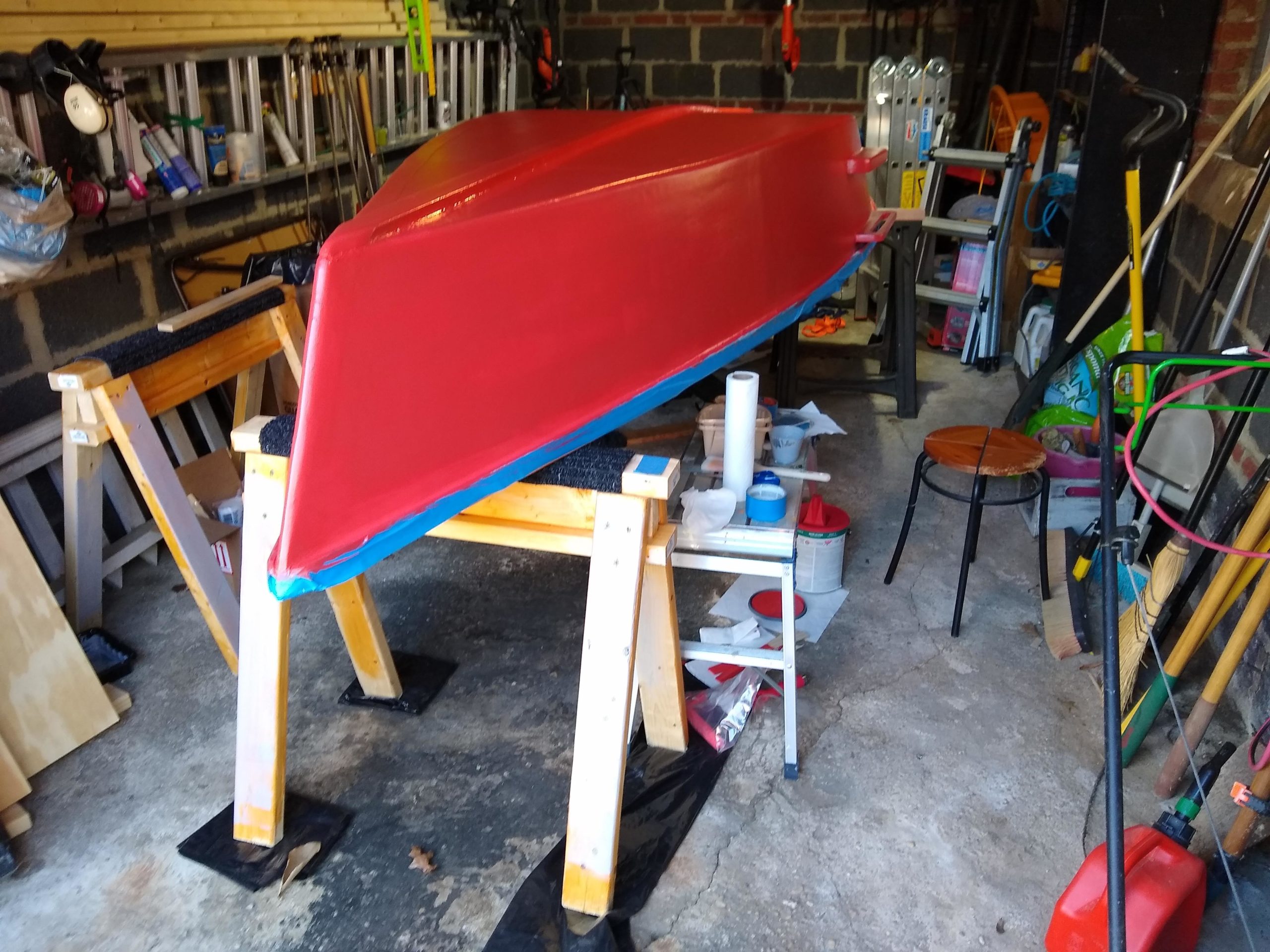
We had such a busy weekend, all I had time for was another coat of red on the outside of the boat.
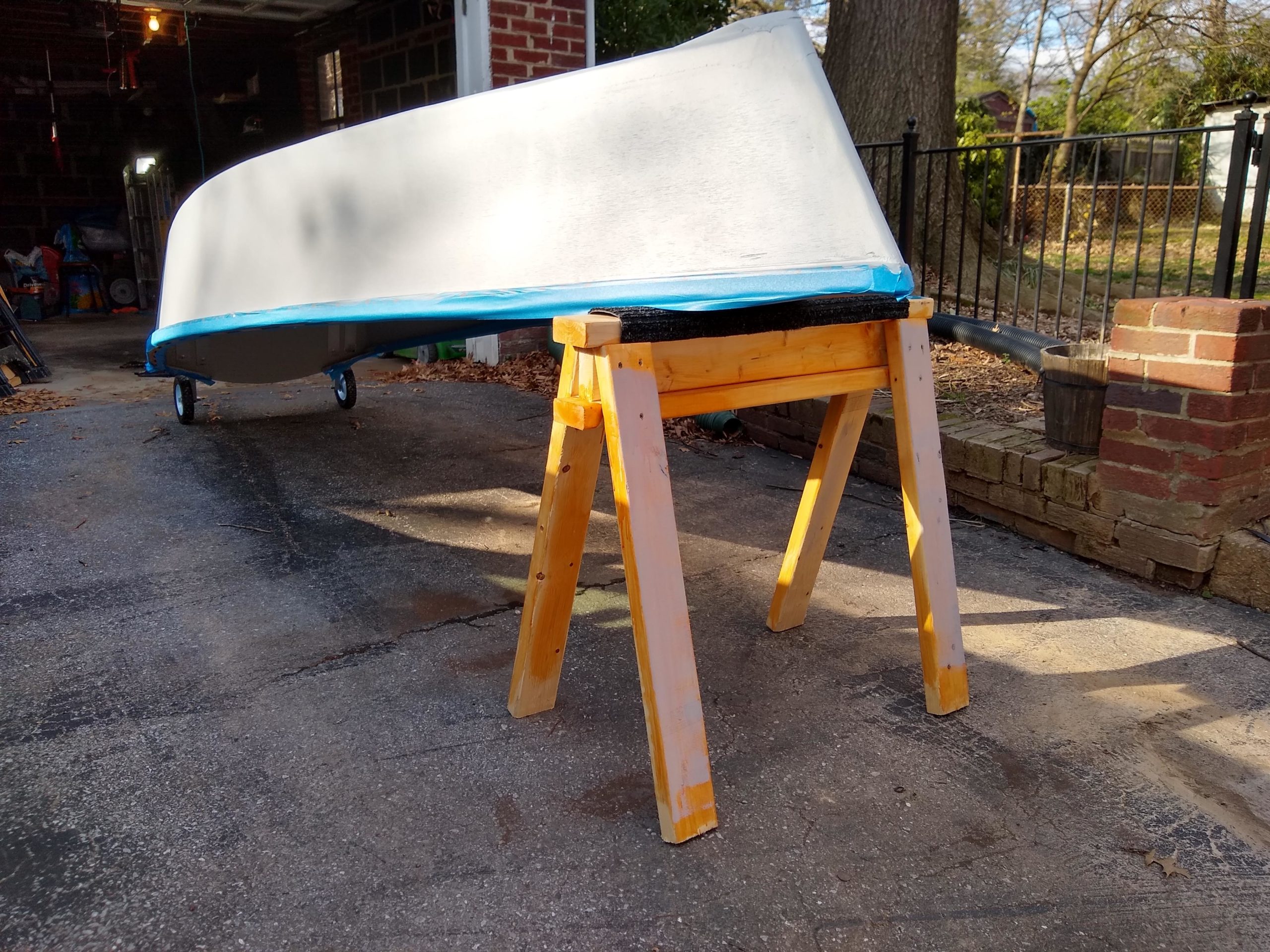
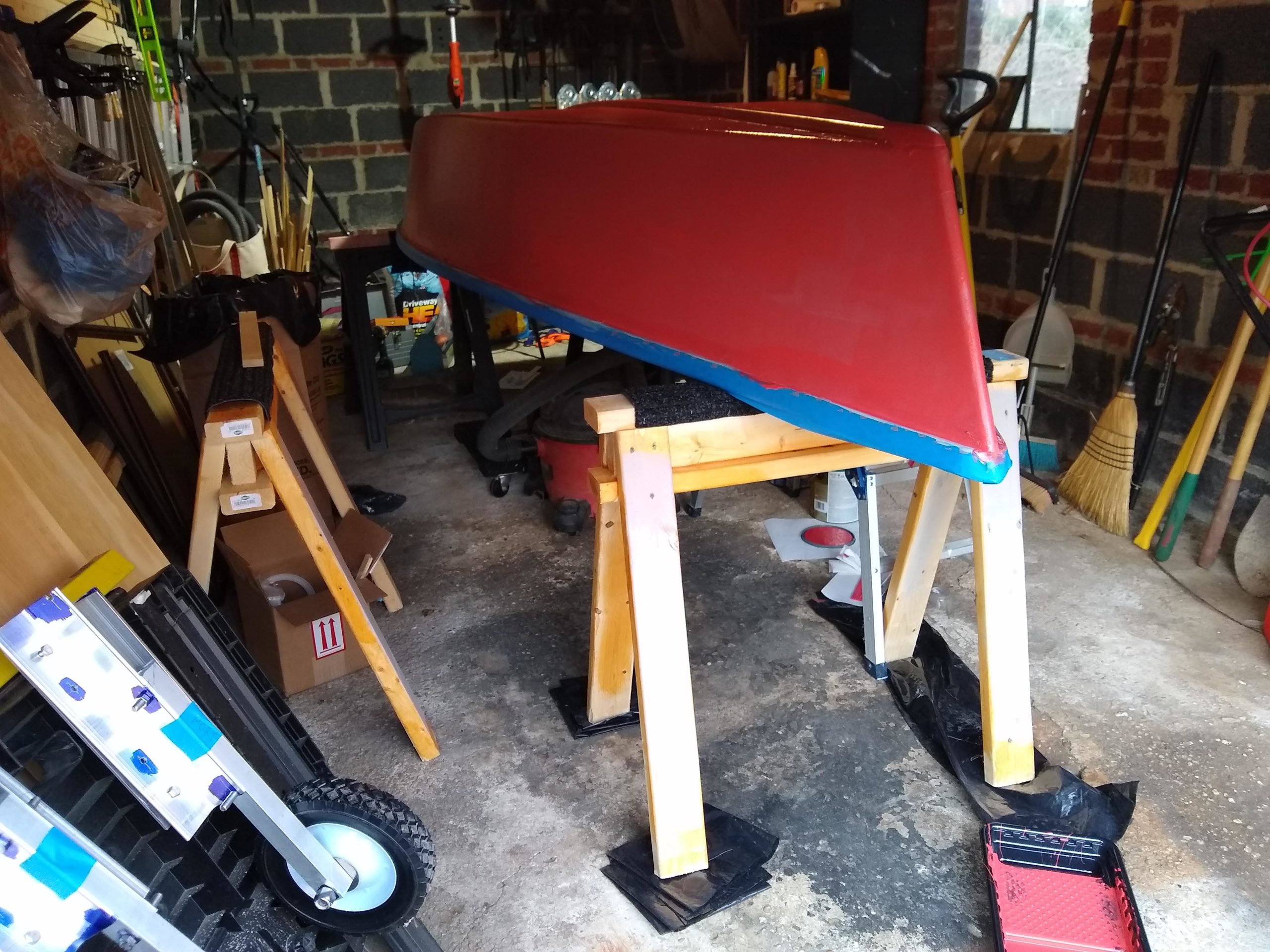
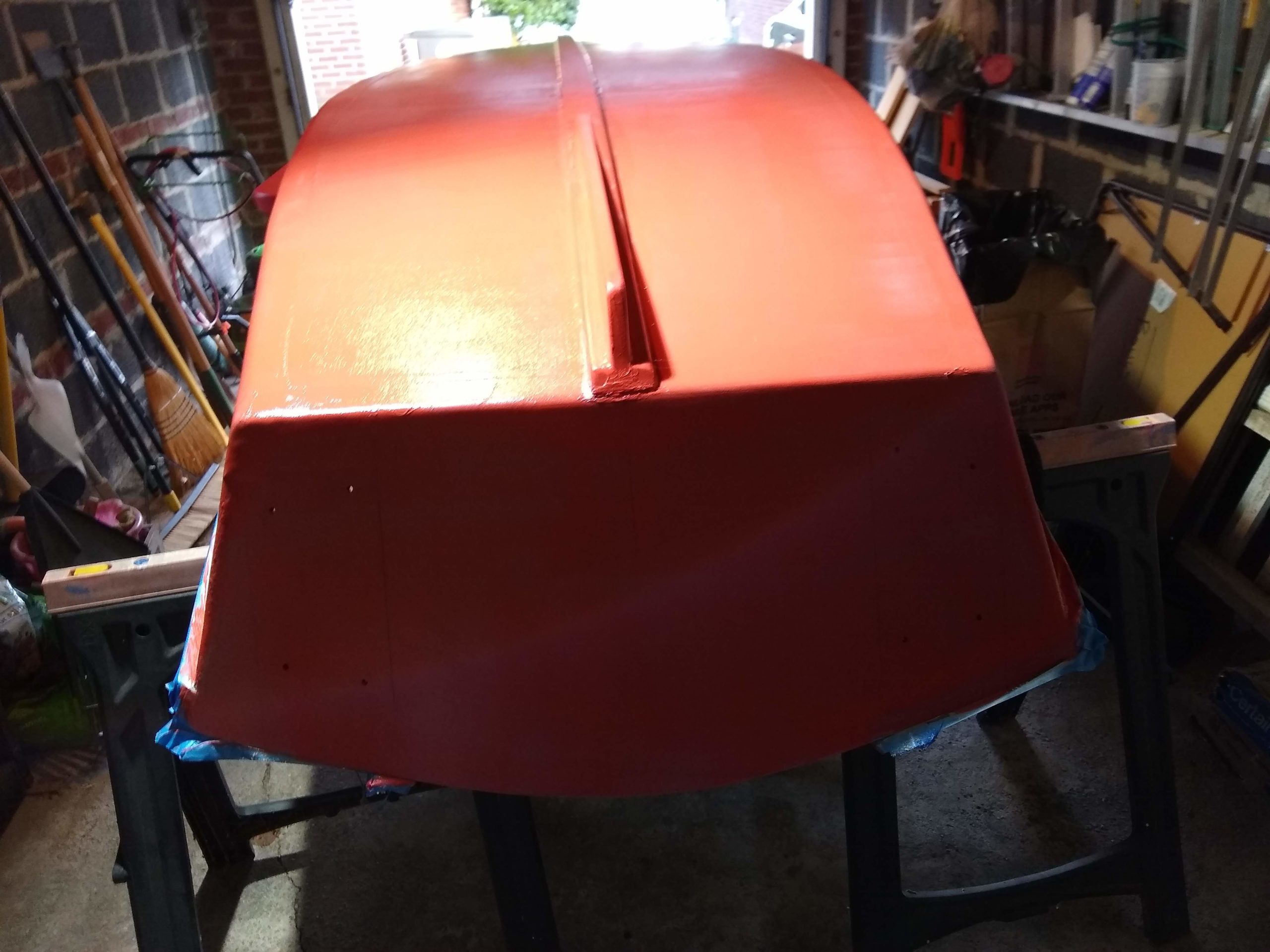
The can wasn’t so full, so I felt like I was better able to stir and mix this time. Coverage seemed pretty good. I’d like to leave it at 2 top coats over the 3 coats of primer. I’m worried that all this paint is going to make the boat heavier than I want, make it too heavy to wrestle on top of the car when I need.
Maybe final red coat
I need to figure out a way to weigh the boat. Either with a couple of bathroom scales, but our scales nowadays are digital, with either the need to tap to get it to start & set to zero or with like an auto shutoff after 5 seconds or so. Or some sort of hunting/fishing scale from Amazon, but do I really want to spend $30 for this? Either I can get it up on the car or I can’t.
There’s also a nifty way to use one scale and calculate by weighing the boat on a trailer in two different positions and plug in the weights and distance moved into a simple formula, but, yeah, it needs a trailer. Sigh.
Dawn thinks I’m nuts, but I’m making my own set of oars. Specifically, I’m building what I call Michalak Oars. (Jim Michalak acknowledges that he based his design on Pete Culler’s oars, so Gavin Atkin calls them Culler-Michalak oars.)
One factor is cost, where I’m splurging on 1 × 8 pine at $22 per board but even the cheapest oars on Amazon or at like Cabela’s are twice that, but furthermore my oars are hopefully going to be better than those more expensive oars. As Atkin says:
The Culler-Michalak method produces a pair of oars at a fraction of the price you will be charged for a single badly balanced and clunky ready-made oar bought from a yacht chandler. So these real paragons among oars are cheap as well as right for the purpose.
Atkin, G. (2008). Ultrasimple boatbuilding: 17 plywood boats anyone can build. Camden, Me.: International Marine/McGraw-Hill.
So I’m definitely going with the great Jim Michalak on the matter.
Making use of 7-1/2″ width versus 5-1/2″
I am making one small change, though, in that I’m using 1 × 8 lumber instead of 1 × 6. I never could make the 1 × 6 size work for the parts in SketchUp. Atkin and Michalak both say it works, but I’m using 1 × 8 anyway, despite it being like $5 more per board. I’m spending $10 in insurance, I guess.
Beautiful pine boards ready for making oars
The President’s Day holiday weekend was great, having the three days, where I bought the boards and got them home on Saturday, got all the parts marked on the boards on Sunday, and cut out all the parts on Monday.
Middle part of oar #1, handle and square upper loom
My local Home Depot only had 4 eight-foot 1 × 8 boards from which to choose my 2, so I got the straightest 2 of the bunch as best I could. I had to wait almost a half hour to even get into the aisle where the boards were stacked, as it was blocked off for … whatever. Maybe carting in more stock or something. I was over buying some rope while I was waiting, which itself took the longest time to get somebody to cut it with the hot knife for me. Sigh.
Middle part of oar #1, lower loom and blade
But anyway I got the pine home and marked it up. It was quite a fun project, as it was in the relatively roomy (and warm) basement instead of the cramped (and nowadays cold) garage. Dawn was off seeing the Maryland gymnastics team meet Rutgers, so I even had Pandora blasting some tunes. (I don’t usually listen to music while working, at least not while I’m using any tool of any kind. But I figure I can hardly get that injured if I’m distracted while wielding a pencil.)
Both oars marked and ready for cutting out
I measured and re-measured and checked my measurements over and over, patiently erasing plenty of errant lines as I plotted out the parts. The worst was when I drew the lower part of the loom an extra 1/8 inch, where I have no idea how I got that wrong, since it’s a plain 30″ length (although a taper from 2″ down to 1-1/4″). But pencil mistakes are not nearly as upsetting as saw mistakes.
Marking oar #2 went way, way faster than the #1
Cutting out all the parts was rather much more challenging. First was that I used a jig saw, where Michalak uses, and recommends, a band saw. He laments that not everyone has a band saw, but he uses one anyway. But, yeah, I don’t have a band saw. Even if I did, though, I guess I’d only have like a 9″ or 10″ bench top band saw, which I’m not sure about maneuvering an eight-foot board around on one of those.
First board clamped and cutting begins
He also says that some folks use a table saw instead, which I do have one of those. But I don’t really see how that would work. Maybe by separating the parts first with a jig saw and then using the table saw to cut out the parts proper? But that’s a lot of long angled cuts, which I can only imagine needs some sort of taper jig on the table saw, since you couldn’t use an angled miter gauge. No thanks.
Oar #1 parts all cut out
So the jig saw wasn’t great, but it was what I could use. The biggest problem was holding the work on my work bench while cutting. That involved a lot of clamping on the edge of the bench, making all or maybe even just part of a cut, and then un-clamping and moving and re-clamping the piece.
Ready to cut oar #2
There was a lot of strategery involved. But it all got cut out.
Oar parts all cut
Next steps are supposed to be gluing the 3-piece sandwiches together and then shaping the oars with plane and rasp and file. I’ve got some alternative ideas to help speed that along. Maybe. We’ll see.
So, it’s kinda like an anniversary, the 52nd week’s blog post.
Happy Anniversary, Boat Therapy!
The actual chronological anniversary of boat building went thoroughly unobserved in the middle of October, whether for the first blog post on Monday 10/15/18 or when I actually purchased the wood at Home Depot on Saturday 10/13/18. I think maybe I was suffering a bit of embarrassment at the time at not having finished building within a year. Heck, I’d originally envisioned that I’d be launching some time in the spring of 2019. So that time came and went, and then a whole year had passed. And I felt kinda bad.
But I’m past those feelings, I hope. I like to say now that the boat takes as long to build as the boat takes to build. It’ll be ready when it’s ready. But I also want to step back and reflect ever so slightly on the time and effort and dollars that it’s taken so far. It’s been much harder than I imagined, and it’s taken much more time than I imagined, and it’s been much more expensive than I imagined.
But, despite all that, or maybe even because of all that, it’s been a far more rewarding experience than I could ever have imagined. I’m grateful for all the things that have gone right and for all of the things that have gone wrong. I’m grateful for my wife Dawn for putting up with me and encouraging me and even for telling me when it’s time to stop for the day and get back to real life.
And I’m also really grateful for the designer of my little boat, David Beede, for the design itself, of course, but also for all of his diagrams and build notes and pictures and encouragement. And for when he said that vision is “the most important ingredient in creating anything.”
If you have a vision you’re set. … Imagine how you’ll feel when you launch your new boat you made with your own hands. Imagine the way you intend to use your boat. Dream a little.
I’ve never been that great at vision. (I even sometimes think that I wouldn’t have started this project if I’d known that it would take this long. So I’m glad I couldn’t foresee that.) But I keep imagining how it’ll feel when I launch my own boat that I made with my own two hands.
(No, not really. I was going to title this Wheels & Red Paint but then had a brief moment of whimsy.) This weekend I installed both wheels proper and started painting the outside with the final red topcoat.
I was eager to take the wheels for a test drive, so I installed the starboard wheel and lowered the upside down stern off the saw horses it’s been resting on for painting. The wheels held up the hull just fine. So, ready to roll.
Both wheels installed
Nervously, gingerly, I pulled the boat out of the garage and into the driveway. The assemblies held. The assemblies did not collapse in a heap. Whew.
First test drive into the driveway
I did cheat a little, however. I cinched a nut around each pin bolt, holding them in the slots tightly, so that they would be much, much less likely to pop out going over a bump or something. I may do this as a general rule whilst rolling the boat around upside down. But I don’t think I can do this when the boat is right side up for launching, or at least not when it goes into the water. I’m worried enough about leaning over from the dock to reverse the wheel assemblies for sailing without having to un-tighten nuts that might be under water.
Formal portrait. Time to roll back into garage and remove.
(Will they be under water at that point? I guess the transom shouldn’t be in the water if the boat isn’t loaded with people yet. Maybe it could work. We’ll see.)
I took a few pics and marveled at my skills, then I wheeled the boat back in the garage and removed the assemblies. It was time to paint it red.
Wheel assemblies removed and stored
The can of red was really hard to mix, though. I stirred and stirred for a few minutes, counting a couple hundred turns clockwise then a couple hundred counterclockwise, but I still didn’t feel like it was enough. I think I might buy one of them fancy propeller attachments for a power drill that mixes paint.
Red paint deceptively glossy
It’ll be easier next coat, though, since the can isn’t as full now. I couldn’t be as vigorous, say, with the stir stick with the can completely full. Not sure if a propeller will solve that problem.
Wheels and red paint
So I slapped on the first coat. It looks a lot shinier in the pictures here than it does in real life. And it doesn’t cover the gray as completely in real life either. It definitely needs another coat. Whether it’ll need a third coat, well, we’ll see about when the time comes, of course.
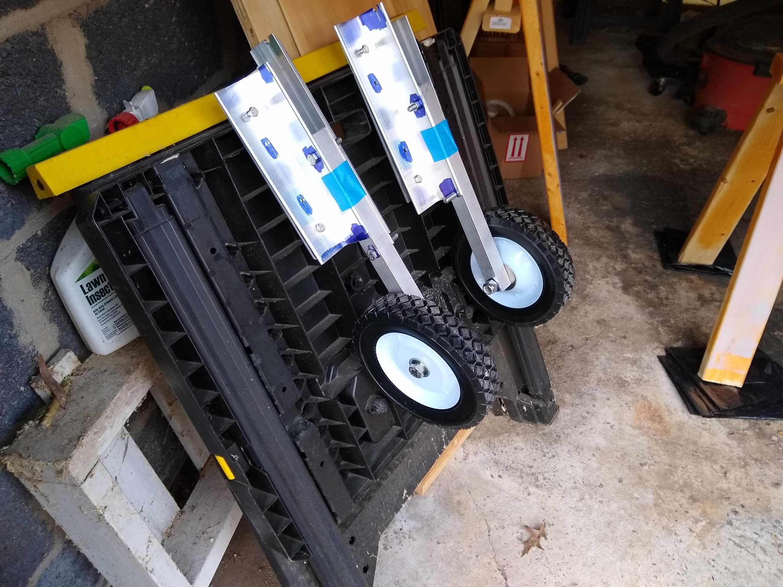
Well, to be fair, it has wheel. Just one wheel. The other wheel isn’t actually attached but rather is still sitting unwrapped on the upside down hull. But the wheel strut assemblies are complete and installed (temporarily) on the transom.
It took much longer than I expected, making these assemblies. Again, to be fair, everything seems to take longer than I expect. But working with the aluminum has been much, much slower, I think mainly because of the filing of rough edges from cutting and drilling.
Drilling new mounting holes in angle stock
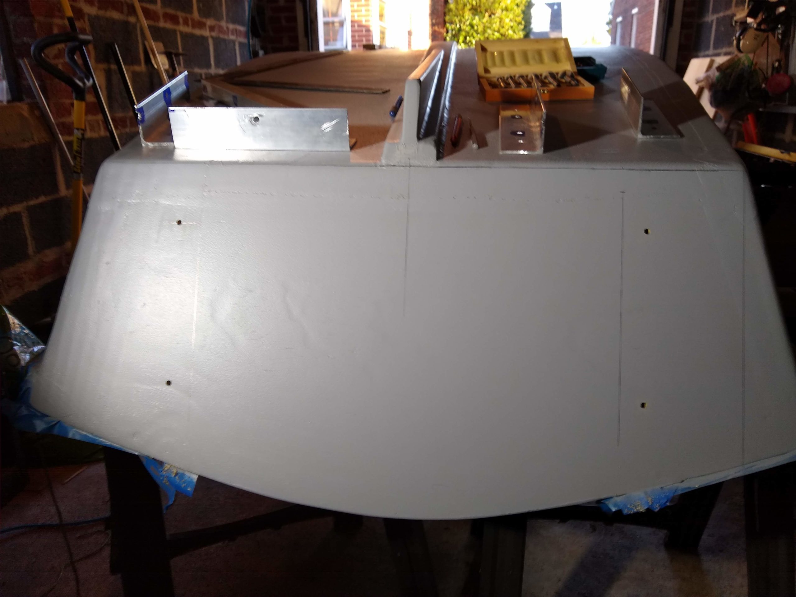
This weekend I did two main final things before being able to mount them to the transom. First was re-drilling new 1/4″ holes in the angle parts. I didn’t make them far enough apart originally. For some reason I thought they’d work best spaced at thirds, where really they should be closer to the ends. I moved each of them half again as close to the ends, this time thinking that this would be far enough but also because I think this spacing will look more symmetrical with the holes that are now going to go unused. I can’t imagine filling them with anything. Wood fill? That would look weird. And, besides, there’s not going to be like a hole in the wood inside them, just painted hull like the rest of the boat. They’re fine.
Cutting flat bar stock on chop saw
Second thing was that I finally cut the aluminum flat bar that will back up the angle parts from the inside of the transom. I think maybe the fact that the stock that I bought was 36″ long might have informed my decision to locate the 1/4″ attachment holes in the angles at 1/3 increments. I wouldn’t need as long of pieces of the flat backing if the holes were closer together. As it was, I think I just had enough stock, cutting 2 pieces at 9-1/2″ length for the long (11″) angle parts and the other 2 at 8-1/2″ for the short parts. (I should have cut them 2 x 10″ and 2 x 8″, but I got a little confused in my calculations. Oh, well. And actually, one of my short parts ended up like an eighth of an inch short, from what I lost from the kerfs from the saw blade from the three cuts. Oh, well, again.)
Cleaning rough edges on flat bar stock
I matched up each of the four pieces of flat bar with one of the pieces of angle and used the angle piece as a template to drill the 1/4″ mounting holes to match exactly. I even dropped a 1/4″ bolt through the lined up holes after the first drill through/in each, to drill the second hole as exact as possible. I felt pretty clever having thought of this method.
Drilling flat bar stock using angle as template
And it worked, too, for three of the four parts when I finally got out to the garage and mounted everything to the transom. Only with the long angle piece on the starboard side did I have to pound the hex bolts into place. Not sure where I went wrong when drilling the holes for that one.
Bolt as register pin for drilling second hole
Speaking of the holes, that was something of a process in and of itself. I had measured where the angle parts were going to line up on the transom, at least side to side for both, with also top to bottom for the long angles. I held those in place first and marked the center of the mounting holes with an awl. (Actually, the first one, that troublesome starboard side one, I traced the circle of the hole with a pencil. That maybe was why that one was the worst fit. I just eyeballed the center with the awl for the other 3 pieces.)
First pilot holes for long angles
I then drilled from outside through to inside with a 1/16″ twist bit, to mark the holes on the inside. Then from inside to outside, I drilled with a 1/4″ forstner bit just like an eighth inch or so in, just to prevent tearout on the inside. Then I finally drilled from the outside through to the inside with the 1/4″ forstner bit but this time with a little drill block to make the hole as perpendicular as I could.
Anti-tearout holes on inside of transom
(I could have, and maybe should have, used the drill block to drill the initial pilot holes, but the drill block only goes down to a 1/8″ bit size, not the 1/16″ that I was using. Only after drilling did I appreciate that I could have used a 1/8″ bit for the pilot holes. But, then again, the holes are all being covered by aluminum parts anyway, so any tearout wouldn’t be visible anyway. But, still, it was the principle of the thing, right?)
Final long angle holes
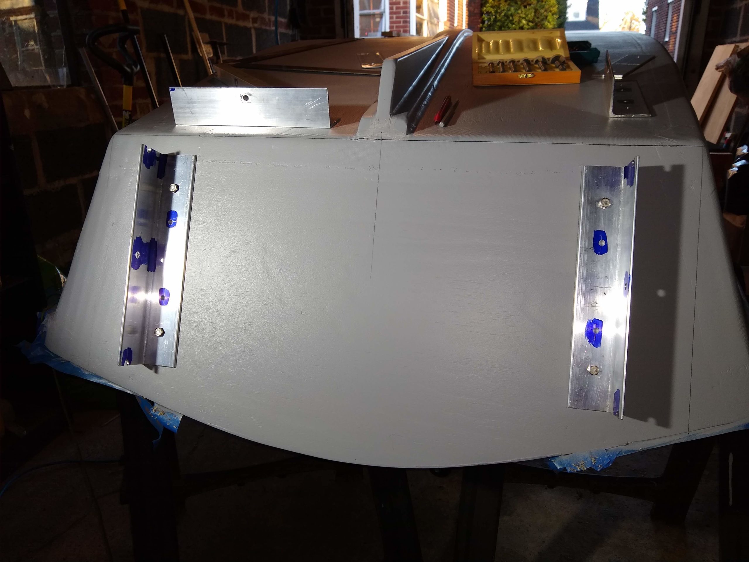
Once the holes were drilled for the long angles on either side, I mounted those two with 1/4″ hex bolts through to the inside through the flat stock and finally nuts cinched down, to be able to site where the holes for the short angles needed to go. For each side I popped a 5/16″ bolt through the center hole of the long angle then through the center hole of the aluminum tube and then finally through the center hole of the short angle. From there I was able to again mark with the awl the centers of the mounting holes and, like with the long angle, drill 1/16″ pilots though from outside, 1/4″ anti-tearout from inside, and finally 1/4″ through from outside.
Long angles mounted
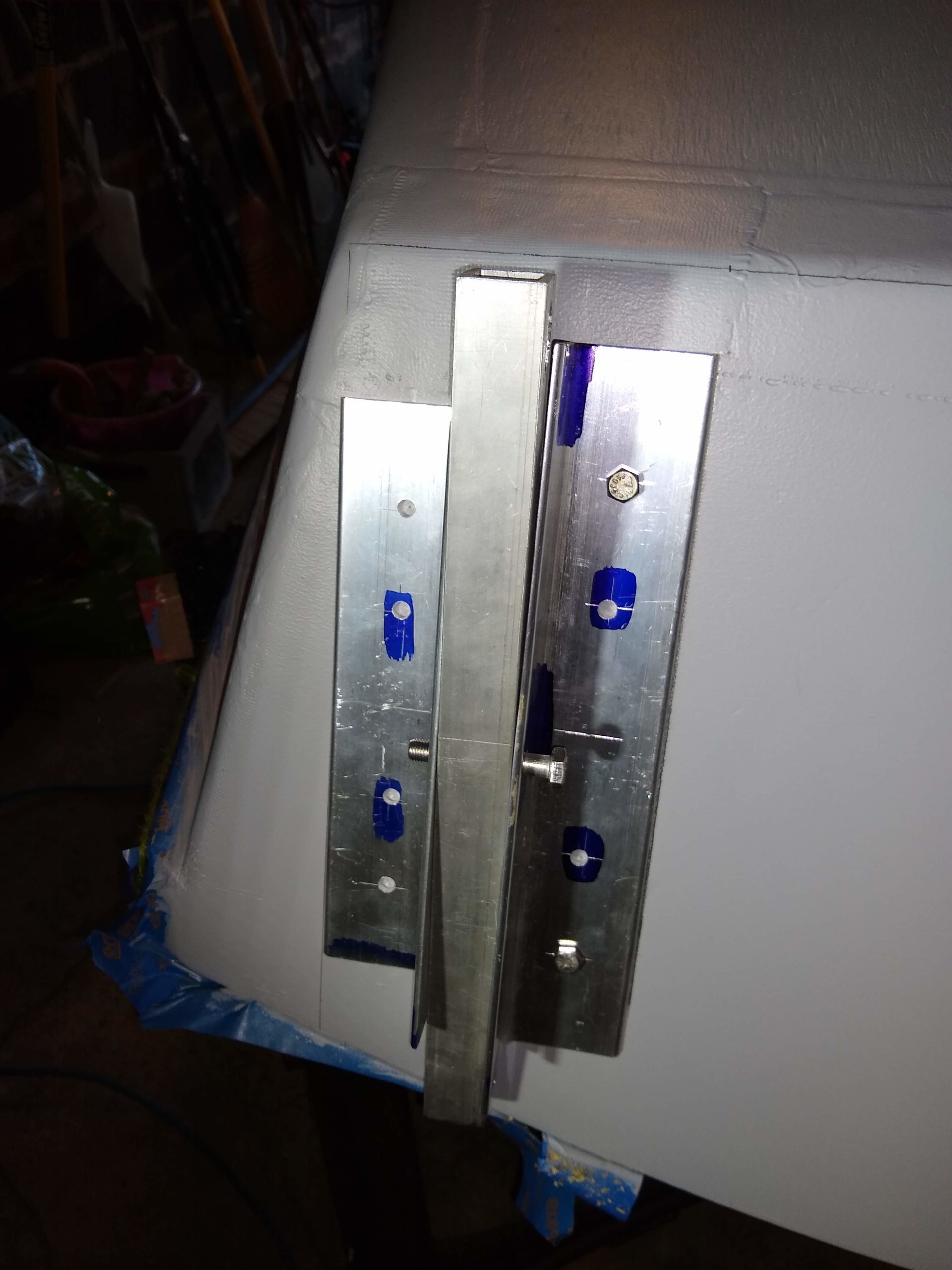
I did a final assembly of each short angle and tube with the spring inside, making sure to thread the first bolt through the center of the short angle through the slot of the tube and not the center of the tube like I did last week, and then through the center of the tube through the other end of the spring. Then I was able to attach this assembly to the transom with the mounting holes in the short angle, threading the short angle center/tube slot bolt through the center of the long angle.
Marking holes for starboard short angle
And finally, finally, I attached one of the wheels. I was a bit terrified at this point, thinking the wheel wasn’t going to clear the hull bottom, but it did. Whew. And that was all I had time to do. It was time to walk the dogs.
My almost 2-wheeler
Next steps are removing the assemblies so that I can paint the insides of the holes with primer. And then I can paint the outside of the boat with its final color. It’s going to be red. And I have to do something with the aluminum parts as well, either paint them or at least remove the blue layout fluid stains. Not sure what I’m doing there. I think maybe some spray paint. But should I spray paint them metal colored or red to match the outside hull or yellow to contrast? I’m just not sure.