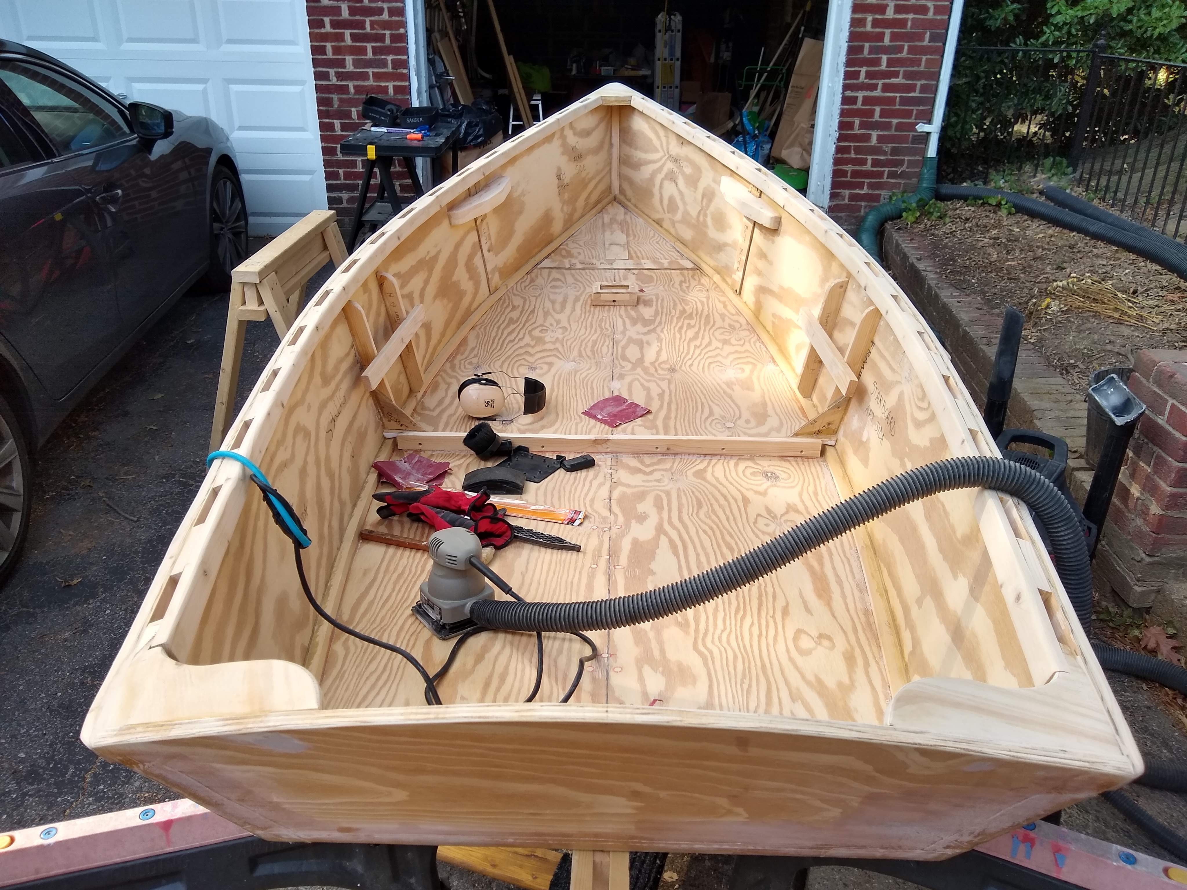
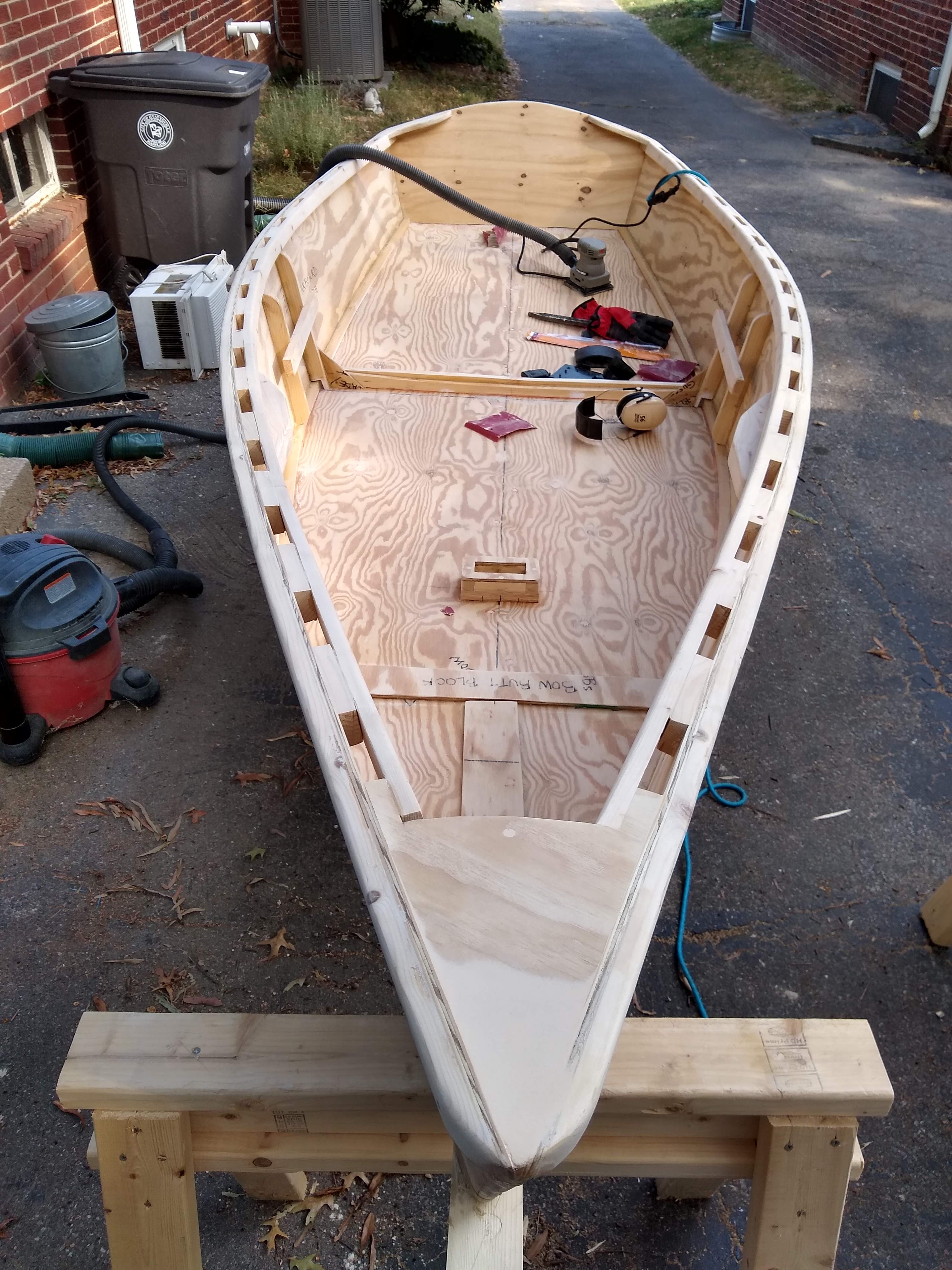
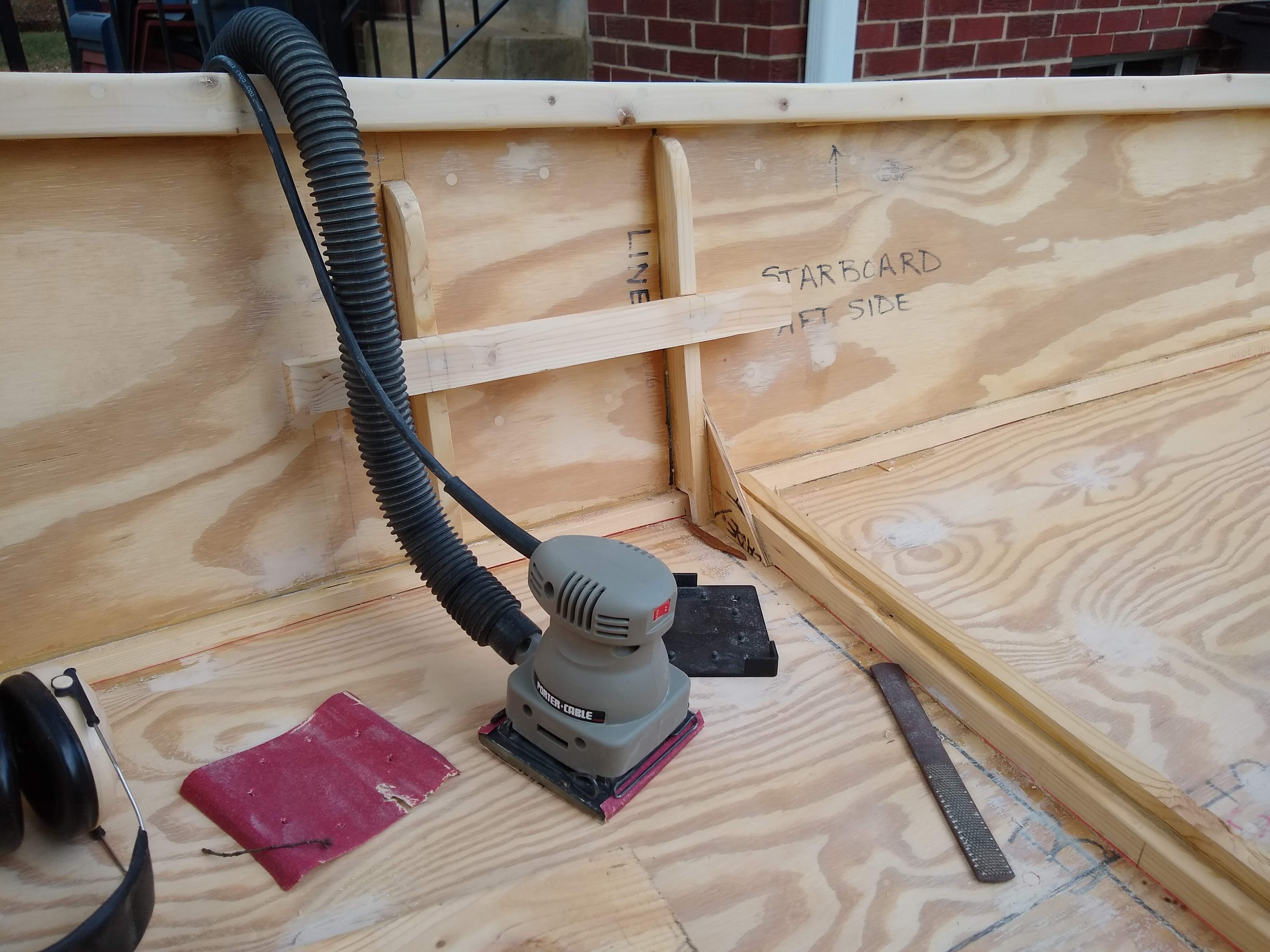
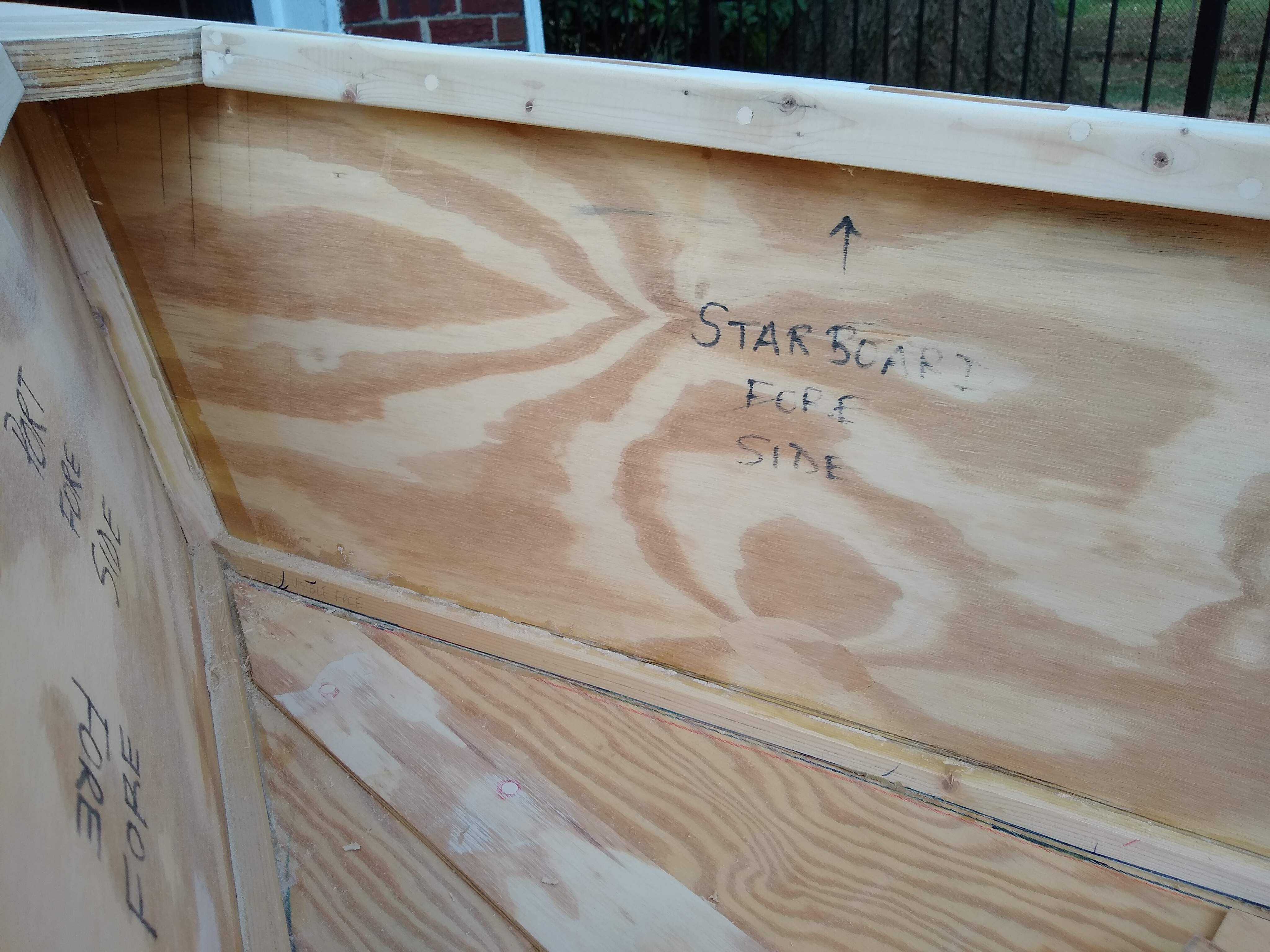
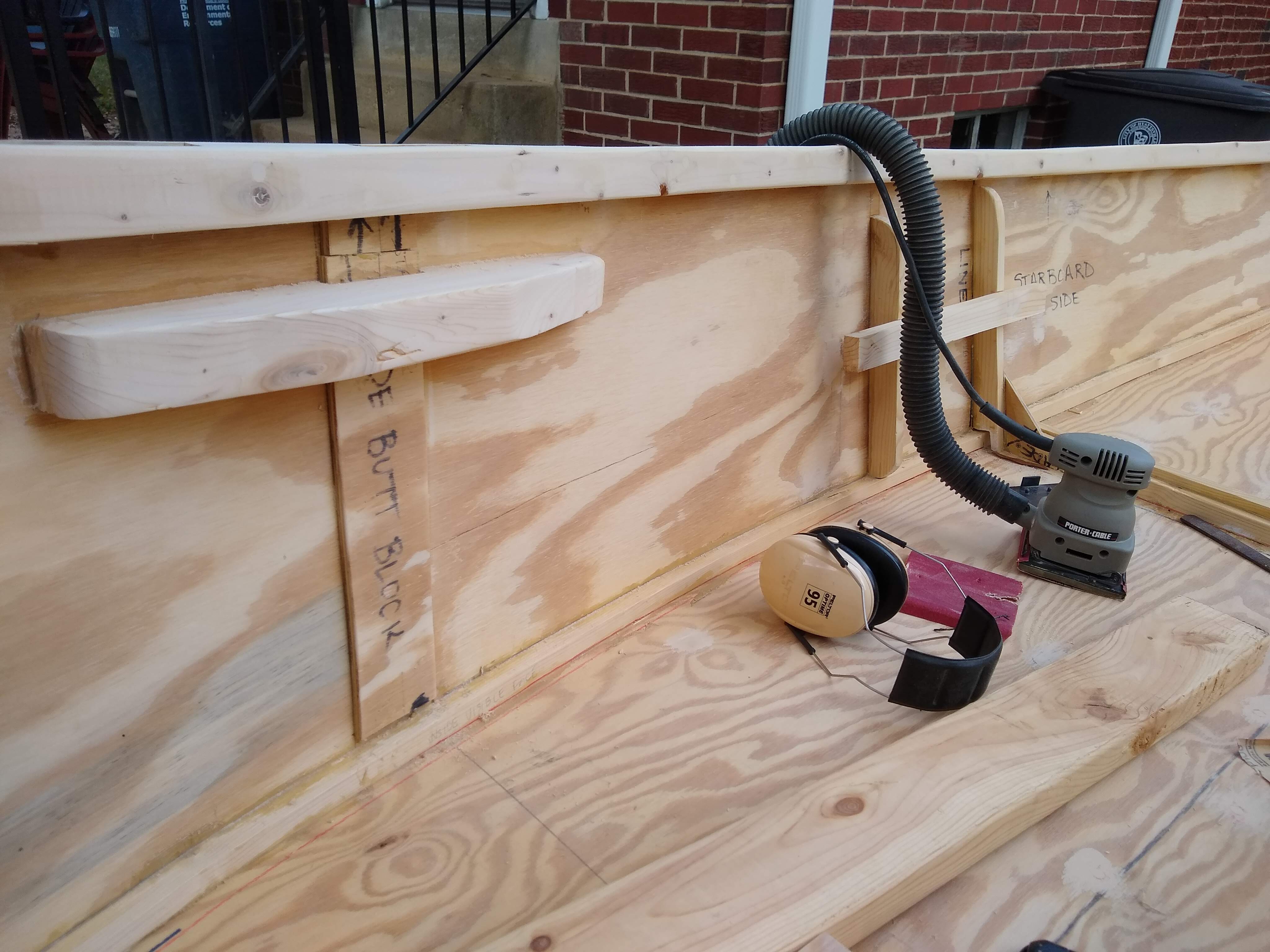
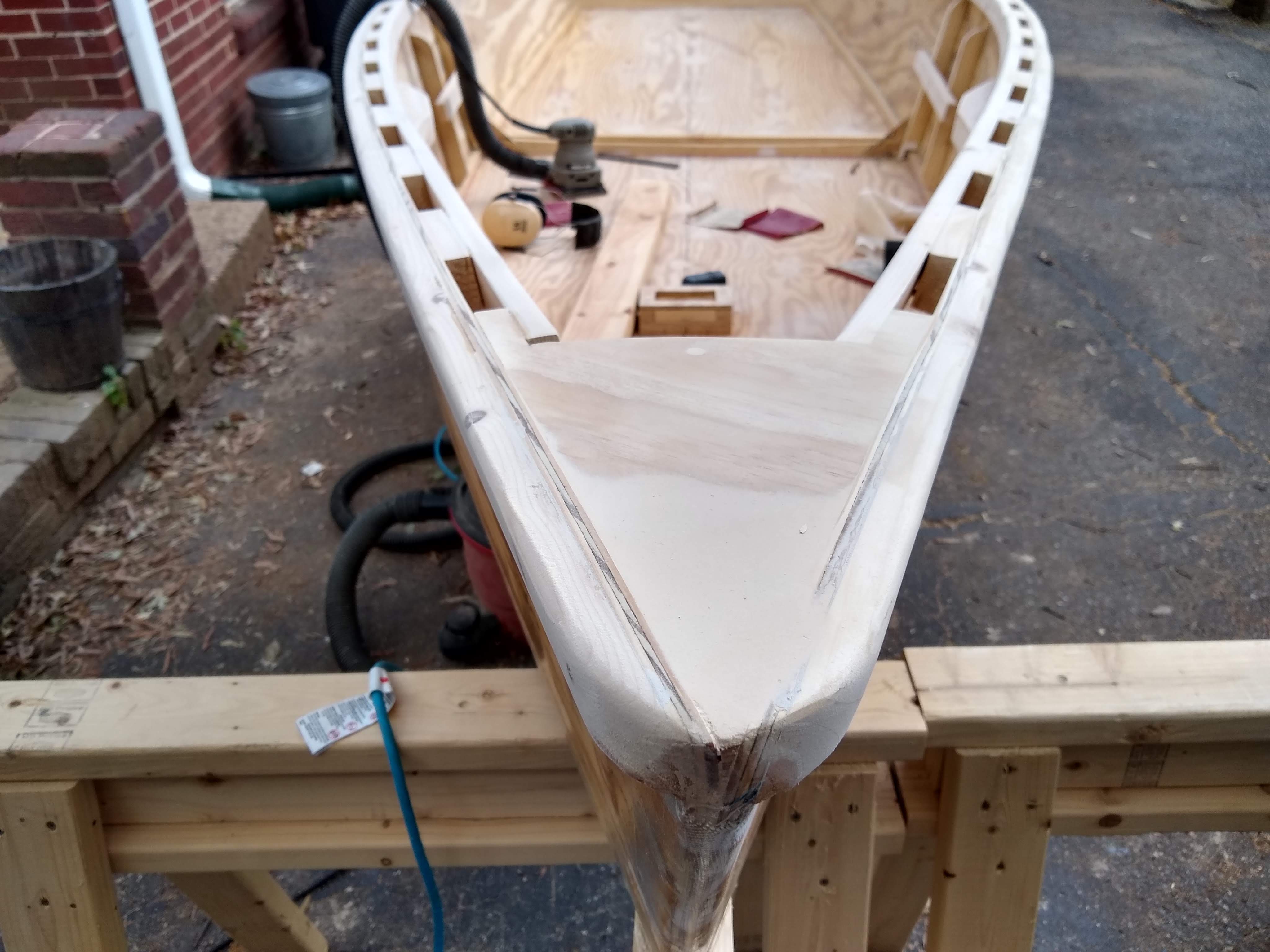
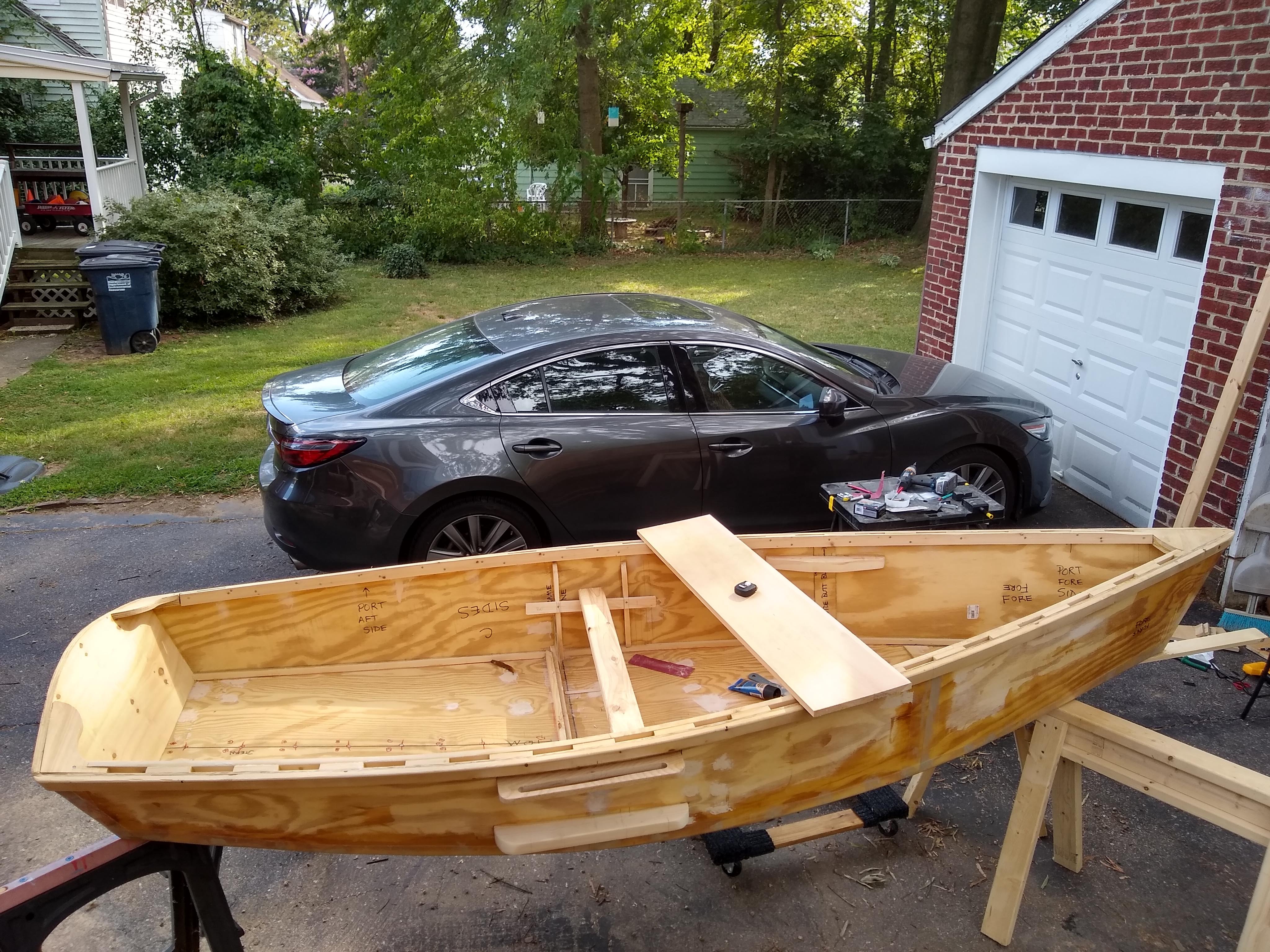
Yes, even more sanding. Another 2 hours of sanding.
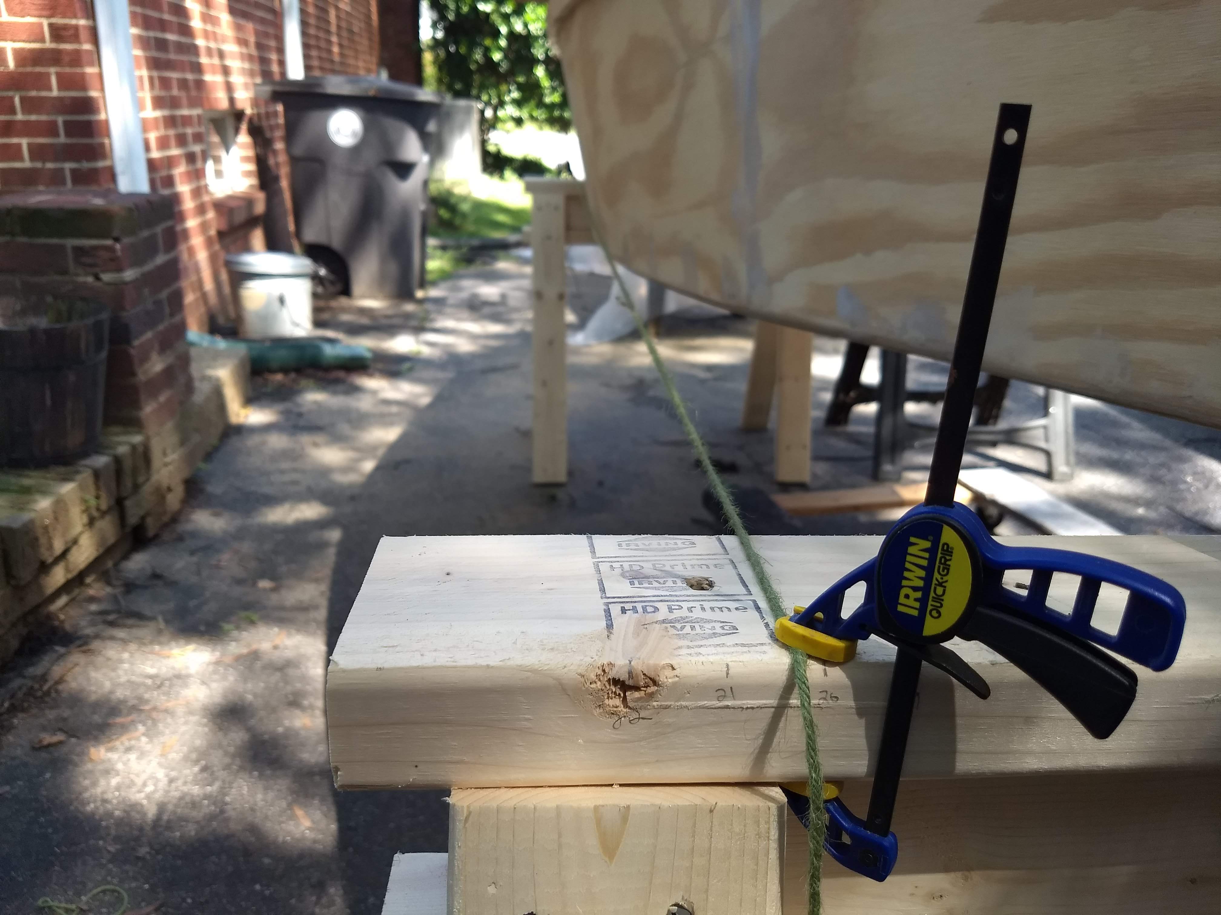
View over the transom makes the boat look short fat stubby
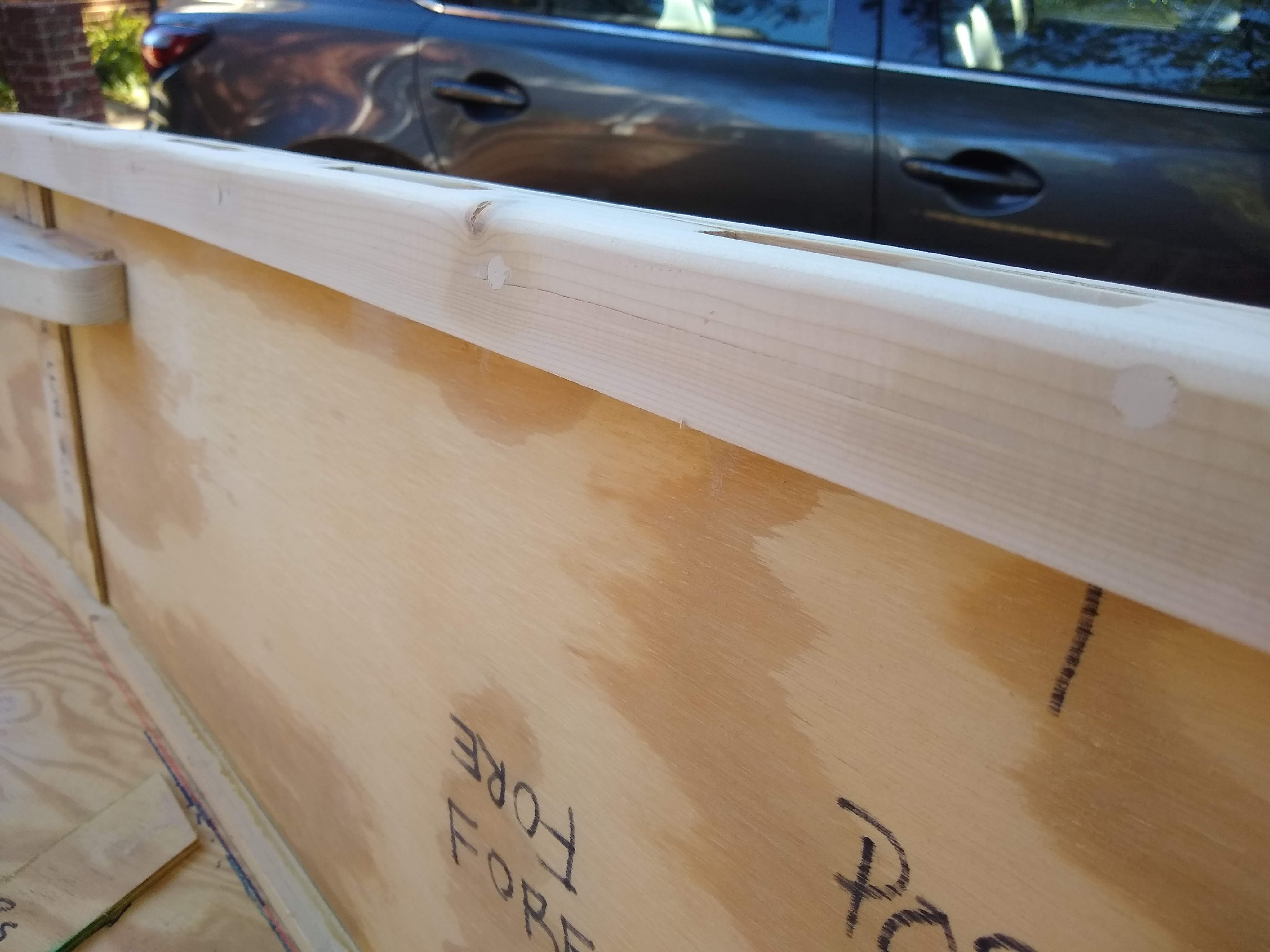
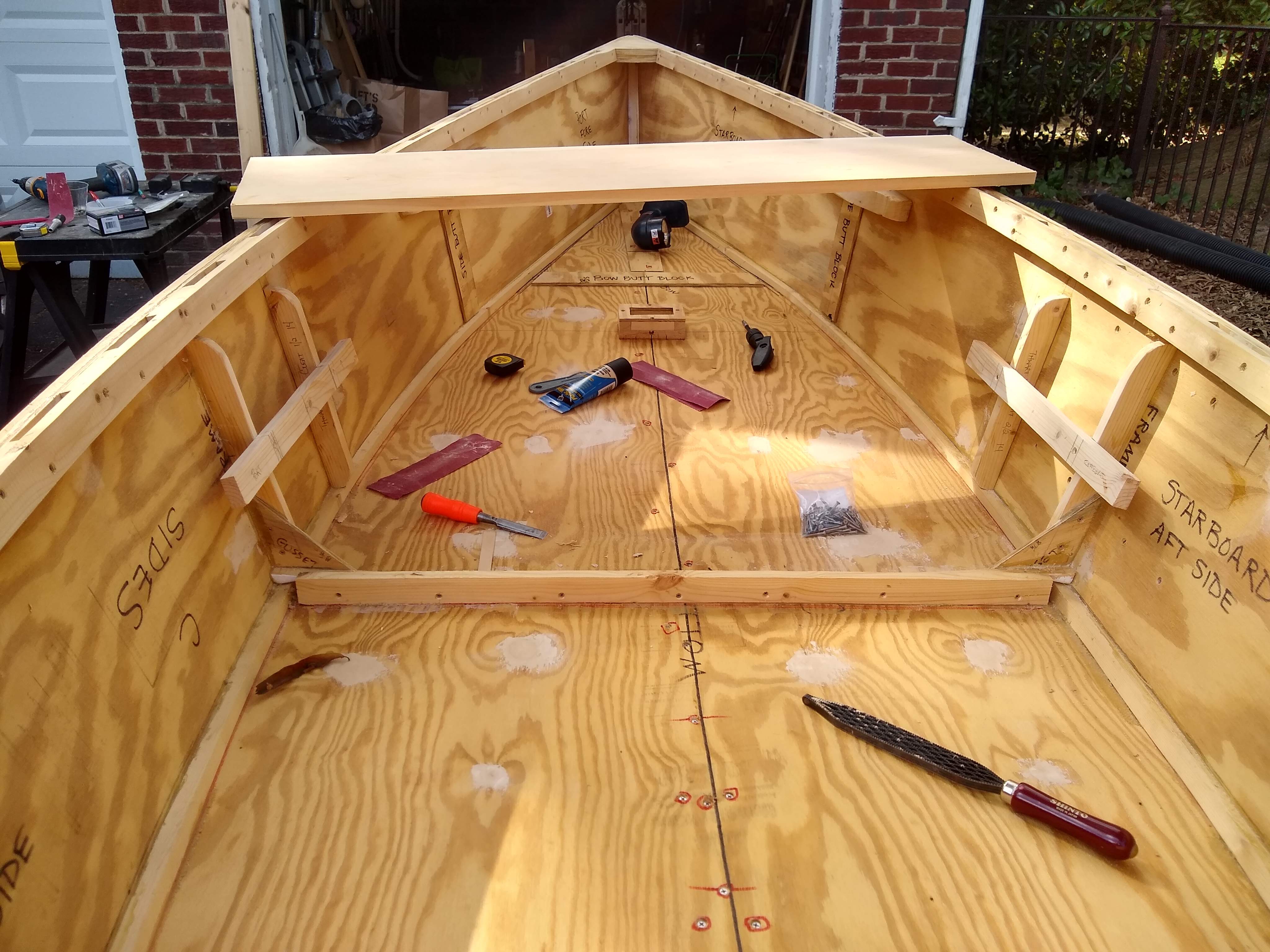
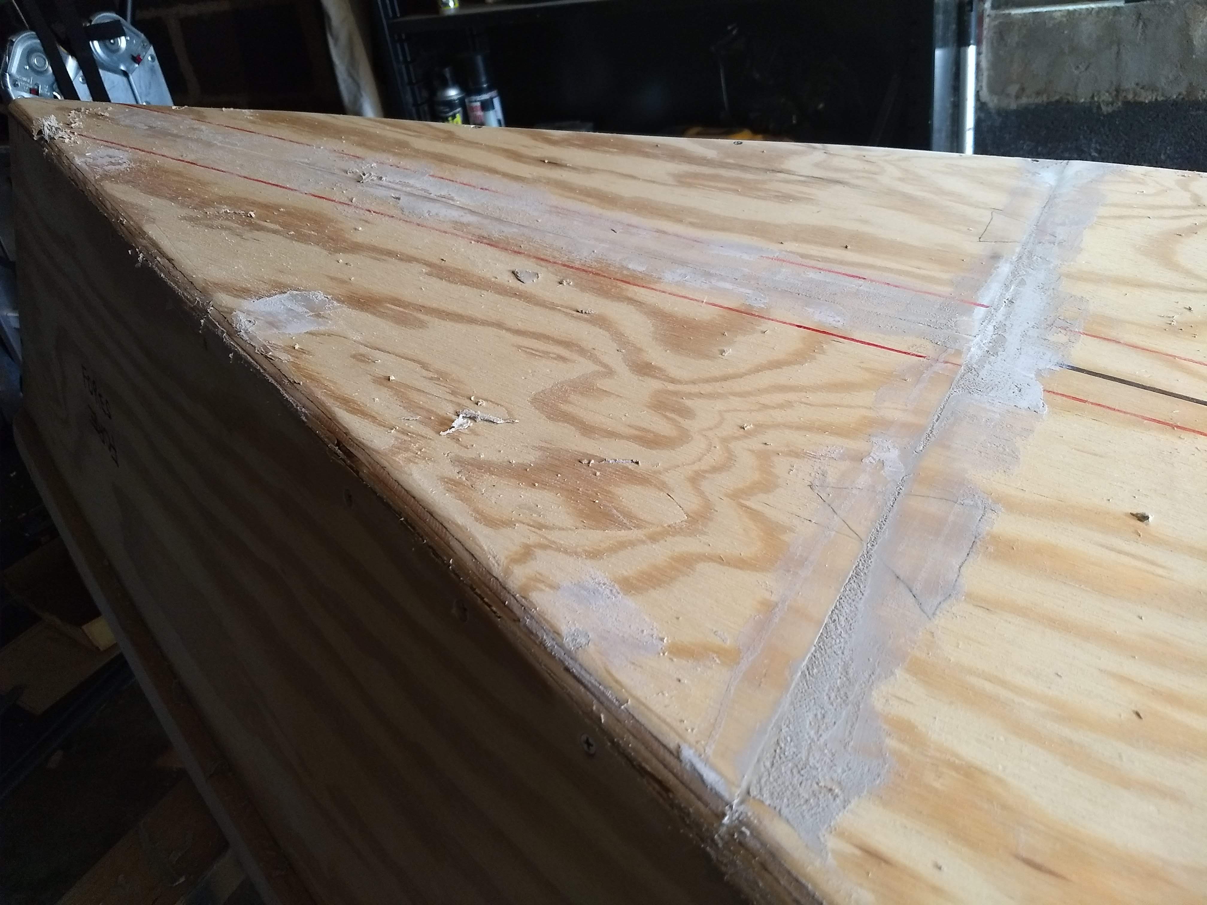
I finished with the 100 grit on the inside. I finished with the 100 grit on everything except the transom on the outside.
View over the bow makes the boat look long and skinny
I’ve decided to leave the bottom, both inside and outside, at 100 grit. I’ll further do the sides, again both inside and outside, with 150 grit. And I’ll finish off the wales, breast hook, and quarter knees with 220, since those’ll all be surfaces that I will grab, or hypothetical passengers will grab, from time to time.
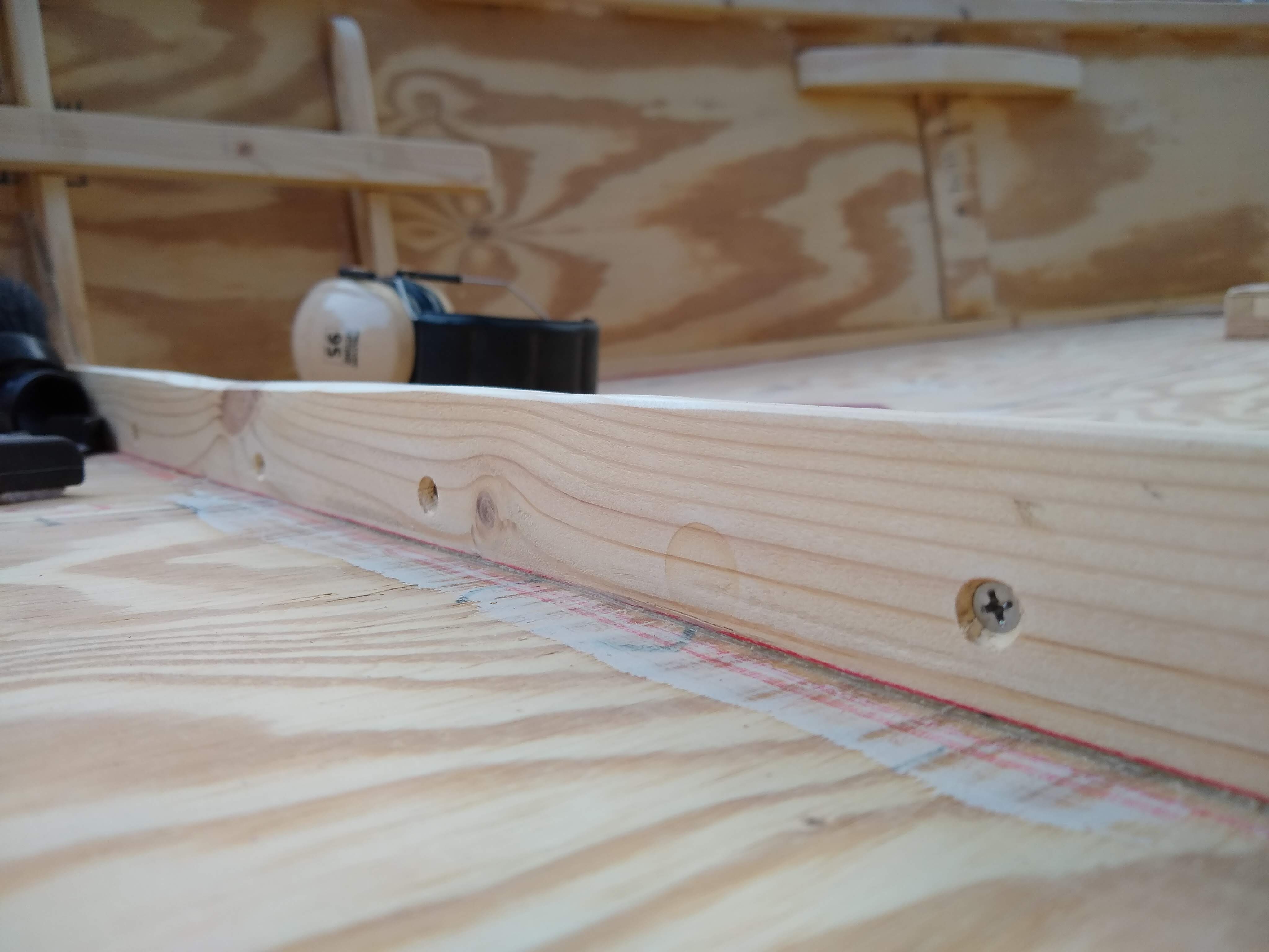
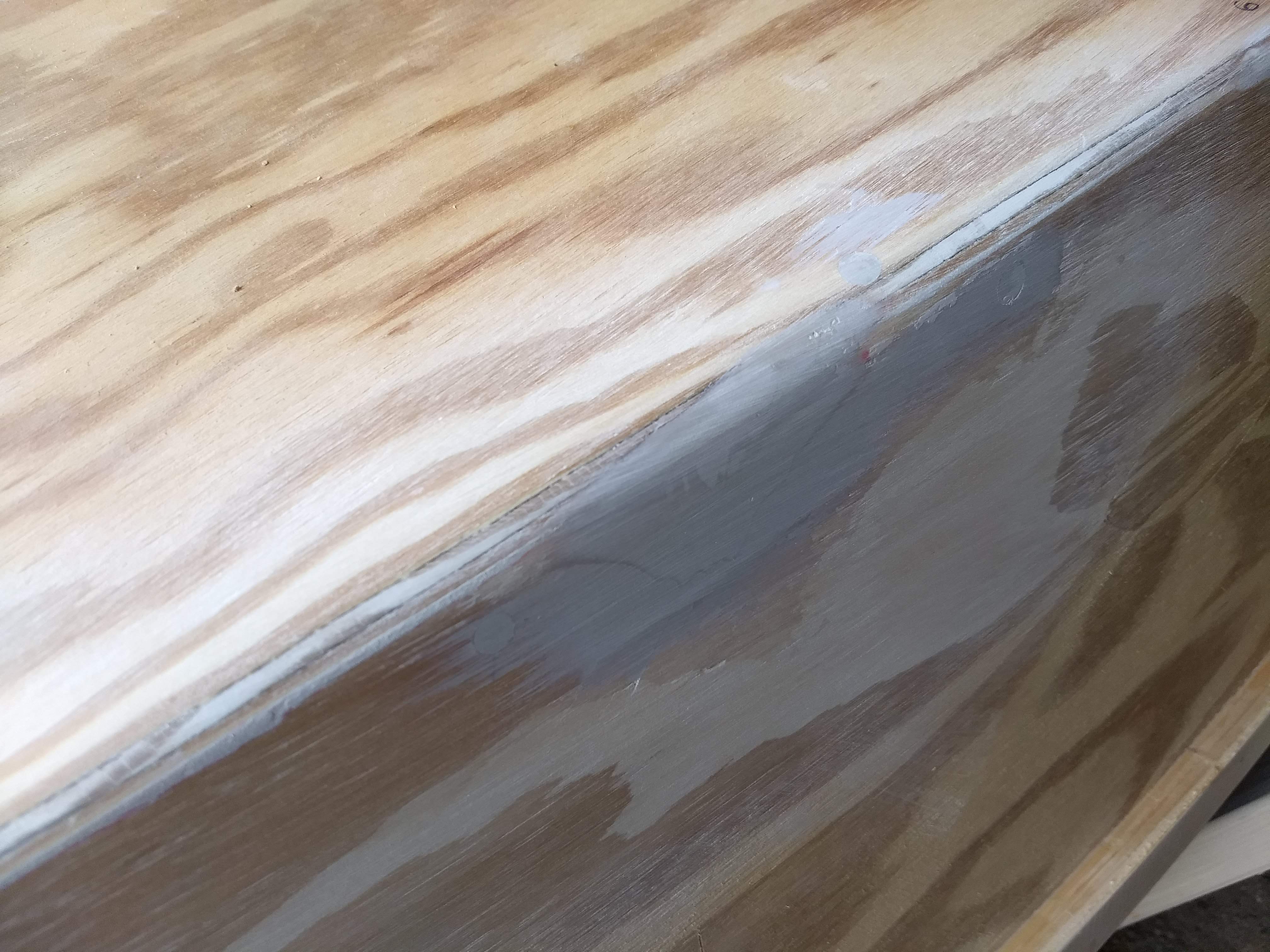
Whoops, unfilled screw holes
Oh, I also discovered, in the course of sanding the inside bottom, a row of screw holes that I’d missed with the wood filler. So I slapped on some DAP on those before flipping the boat over and starting on the outside hull.
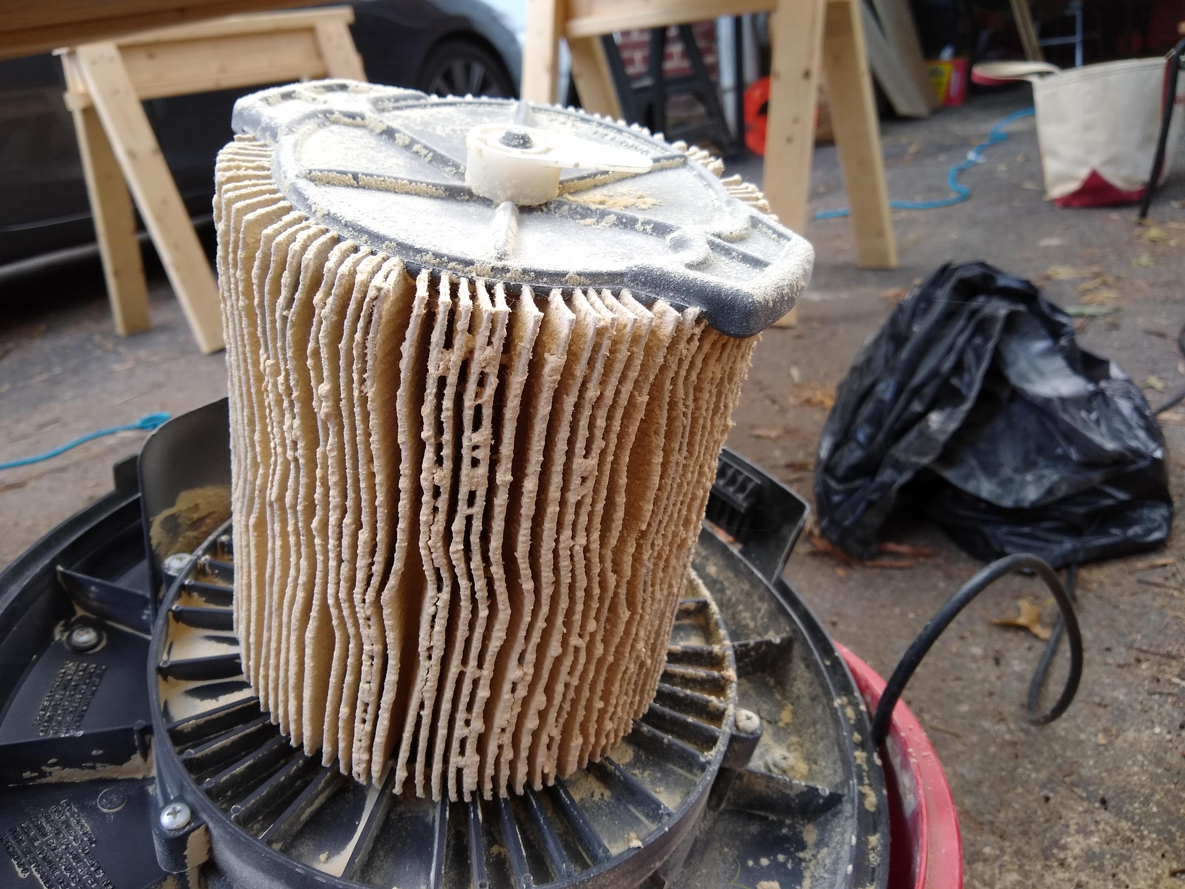
Shop vac filter gets filled with sanding dust
I finally started sanding the glassed chines on the outside. I’d been worrying over doing that for weeks and weeks. The 100 grit on the pad sander didn’t seem to cut through it as drastically as I had been worrying that it would do. So I was able to comfortably cut down the grid pattern of the tape, while holding the sander parallel to either the side or the bottom, without cutting through the rounded corner that seals the seam which is the reason for glassing the chines in the first place. It’ll look a bit rough, in that it’ll be obvious that the chines are glassed even after it’s painted, but it’s a good compromise, I think.
I had filled the interior screw countersinks with DAP wood filler last week, albeit roughly, in globs basically, so this week I set about scraping off the excess and sanding the fills smooth. Most of the fills sanded down to neat little circles, but a couple times all the filler came out somehow attached to a glob. And I found a screw hole or two that I had missed when filling. Whoops.
Scraping, sanding, vacuuming inside the boat
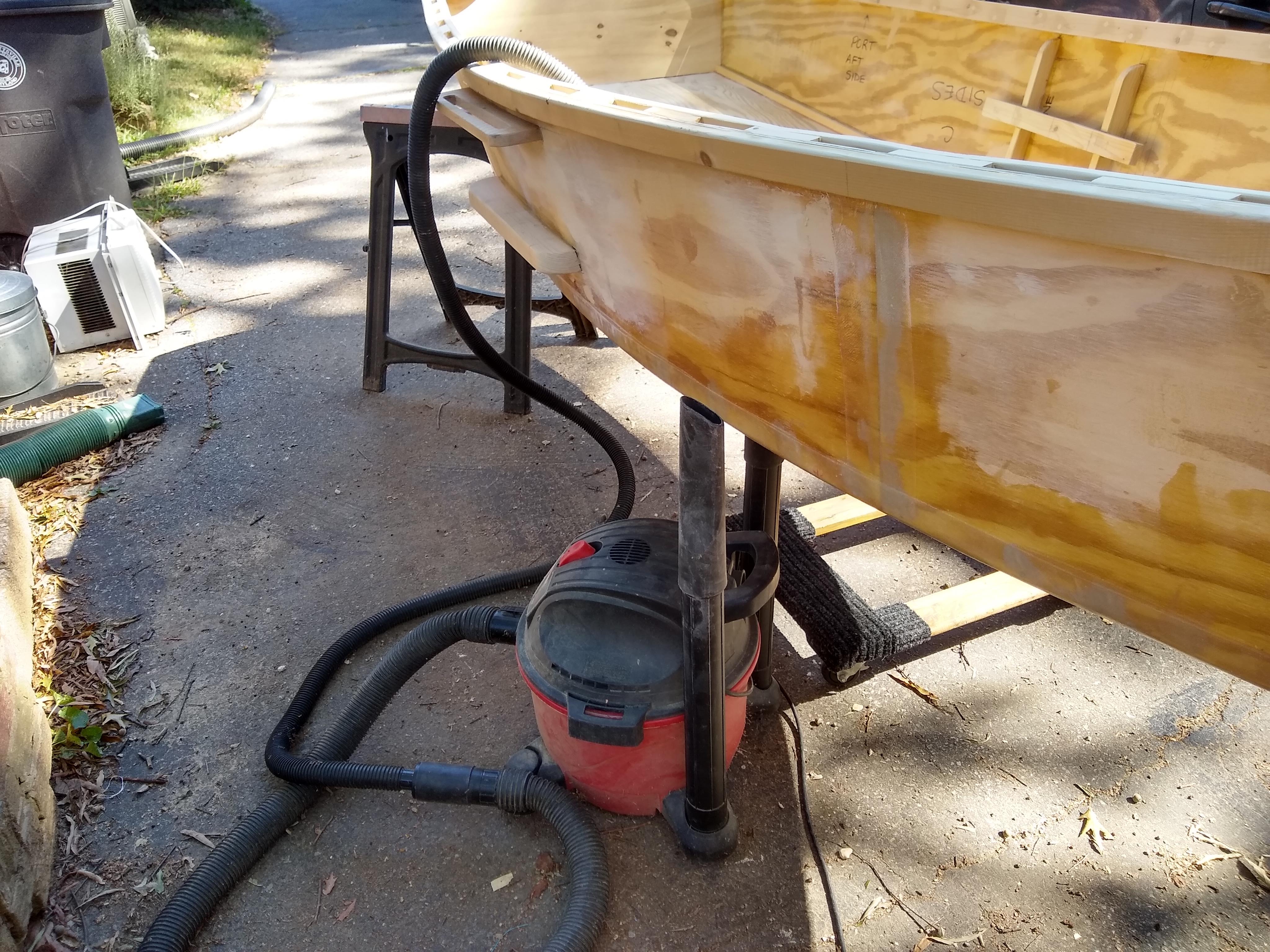
Having started sanding, these screw holes with a hand block and 100 grit paper, I soon found the upright boat filled with globs of filler and a lot of sanding dust. So I hauled out the shop vac from the basement and vacuumed out the boat. Then I started keeping up with the dust with the vacuum going as I sanded.
Shop vac
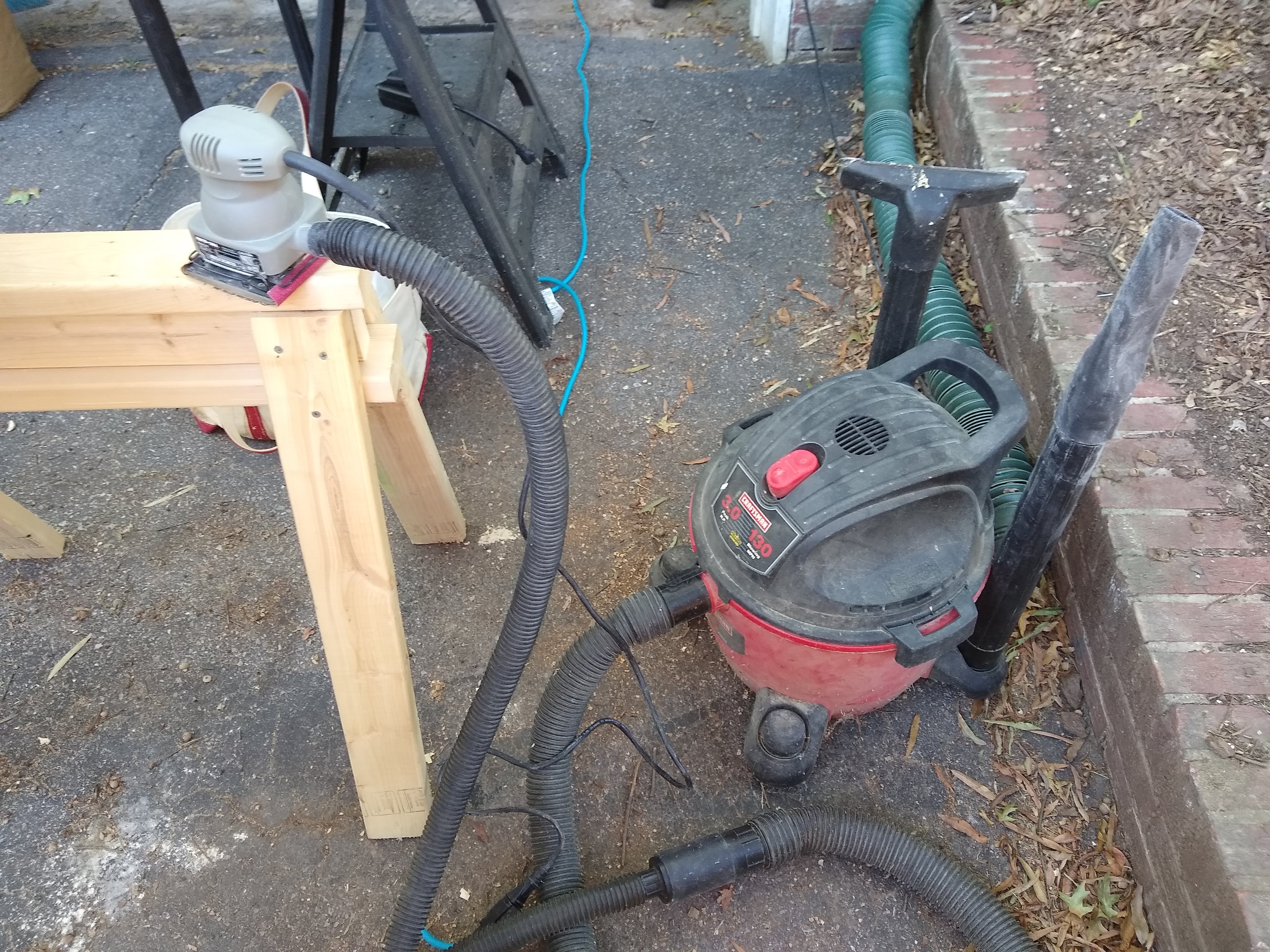
And then finally I brought out the big guns, as it were, in this case the quarter sheet pad sander, which has its own dust collection port, so sanding went a lot faster and the dust collection was no longer a two-handed operation.
Pad sander and shop vac
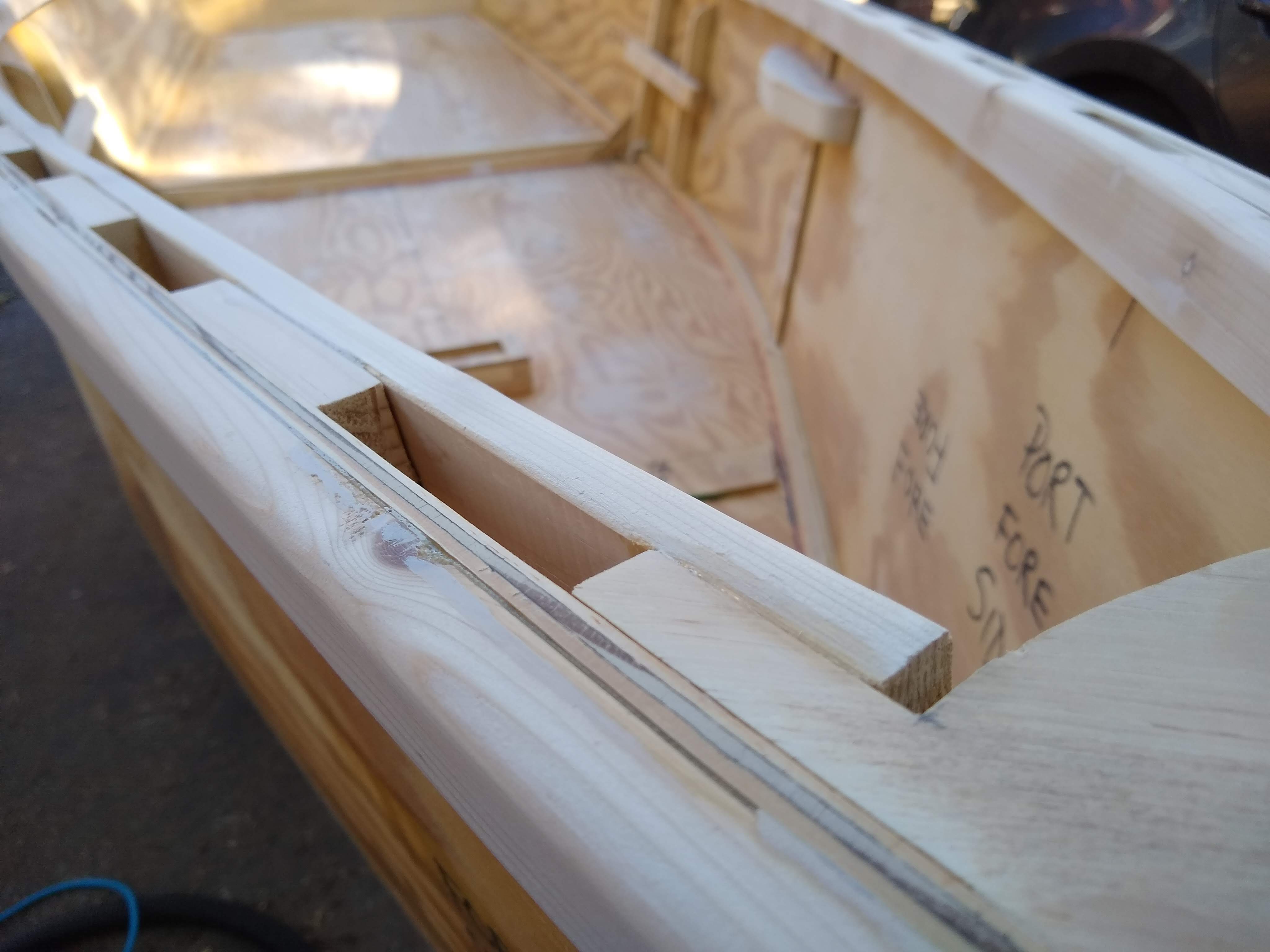
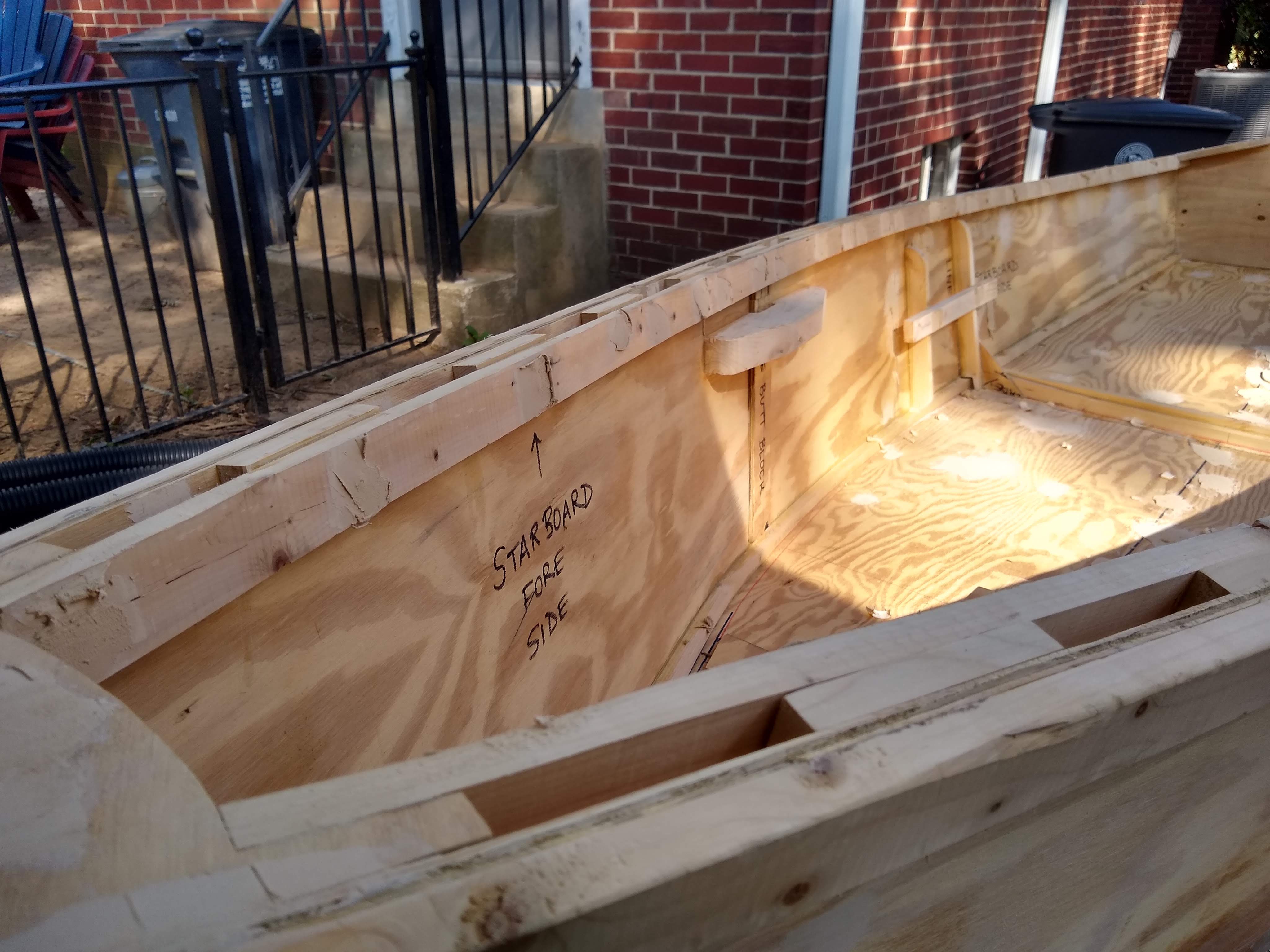
Going along the inwales with the sander, I decided that I didn’t like the unevenness of the inwales in relation to the inwale spacers, where sometimes the inwale stood a little proud above or below the spacer. So I went around the boat with the trusty rasp and evened them out. Then I went back with the pad sander to smooth out the tool marks that remained.
Smooth gunwale
All in all I finished with the 100 grit on the front half of the wales, both inwales and gunwales. The sanding is taking longer than I had imagined, but I’m really liking the results. I had long ago declared that I was embracing the roughness of the first time boat build, but I’m now kinda admiring how un-rough it’s starting to look. So I’m taking extra time in sanding, hoping that the paint job will look better.
Am just about out of things to do before sanding and painting. Don’t think I can put it off much longer.
I did finally glue on the thwart supports, which are (I think) the final parts that are to be permanently attached to the hull. There are many more parts coming, what with mast and yard and boom and lee board and tiller and rudder. But none of those are going to be permanently attached to the hull.
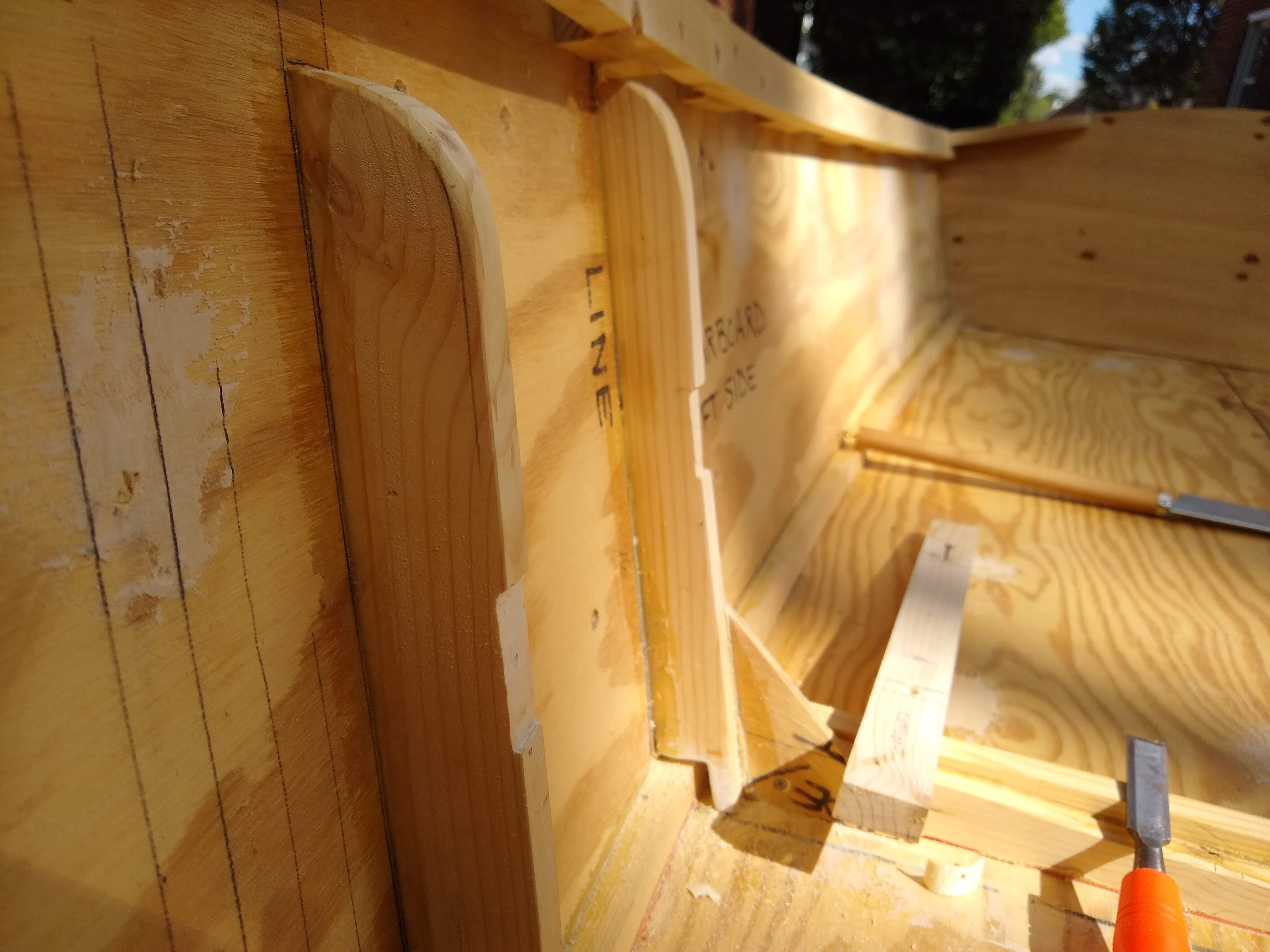
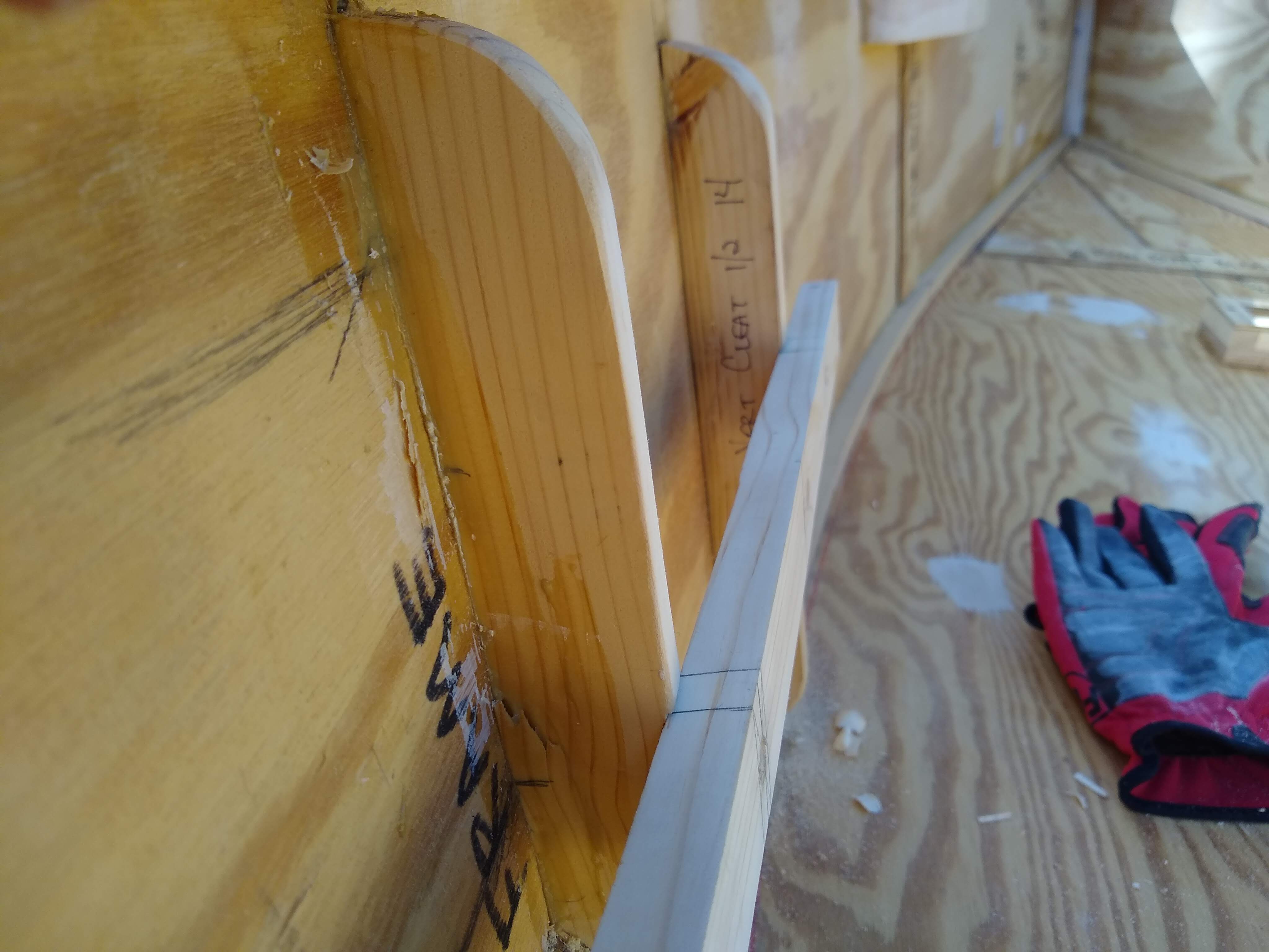
Notching the starboard thwart vertical support and frame
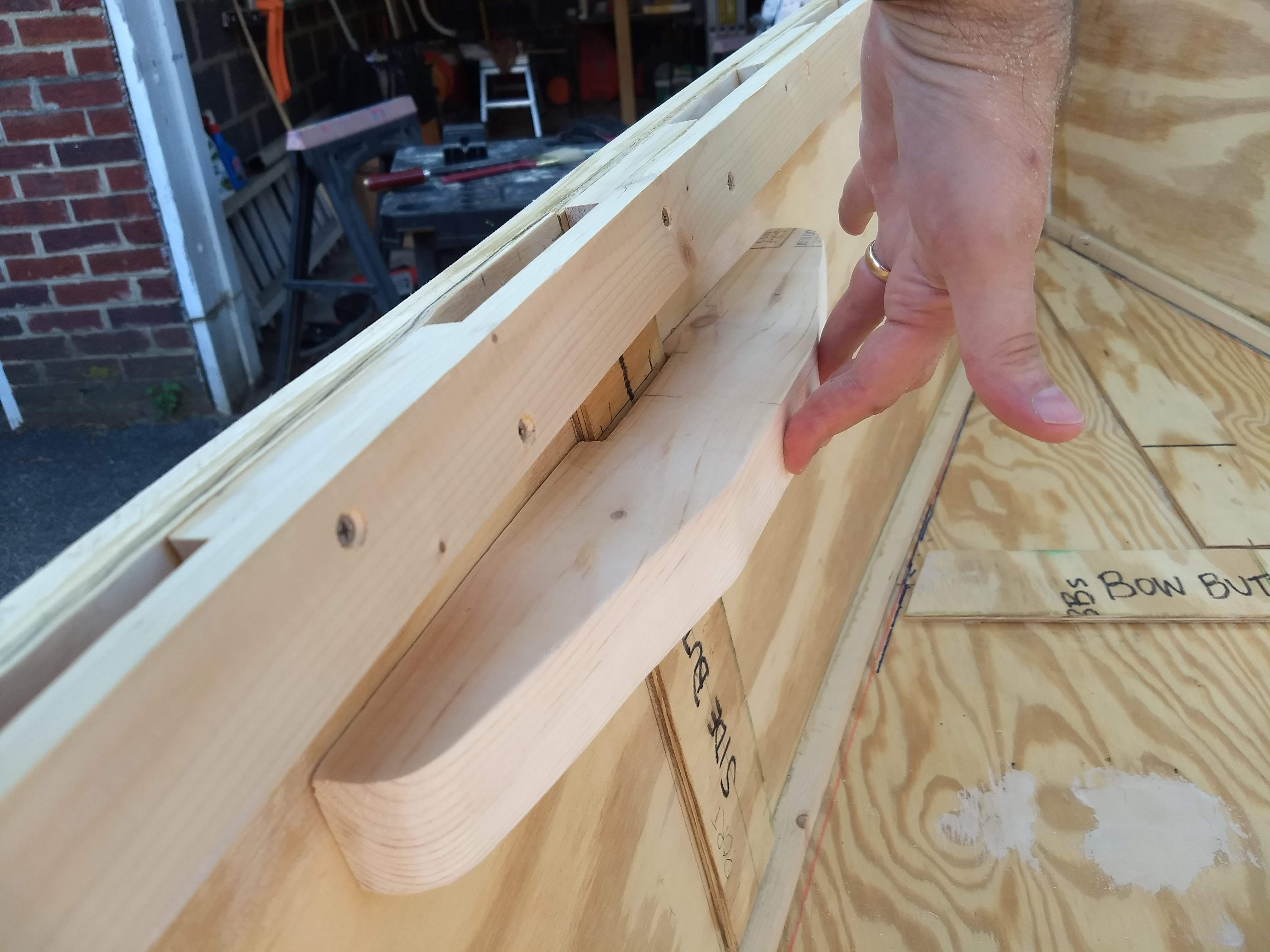
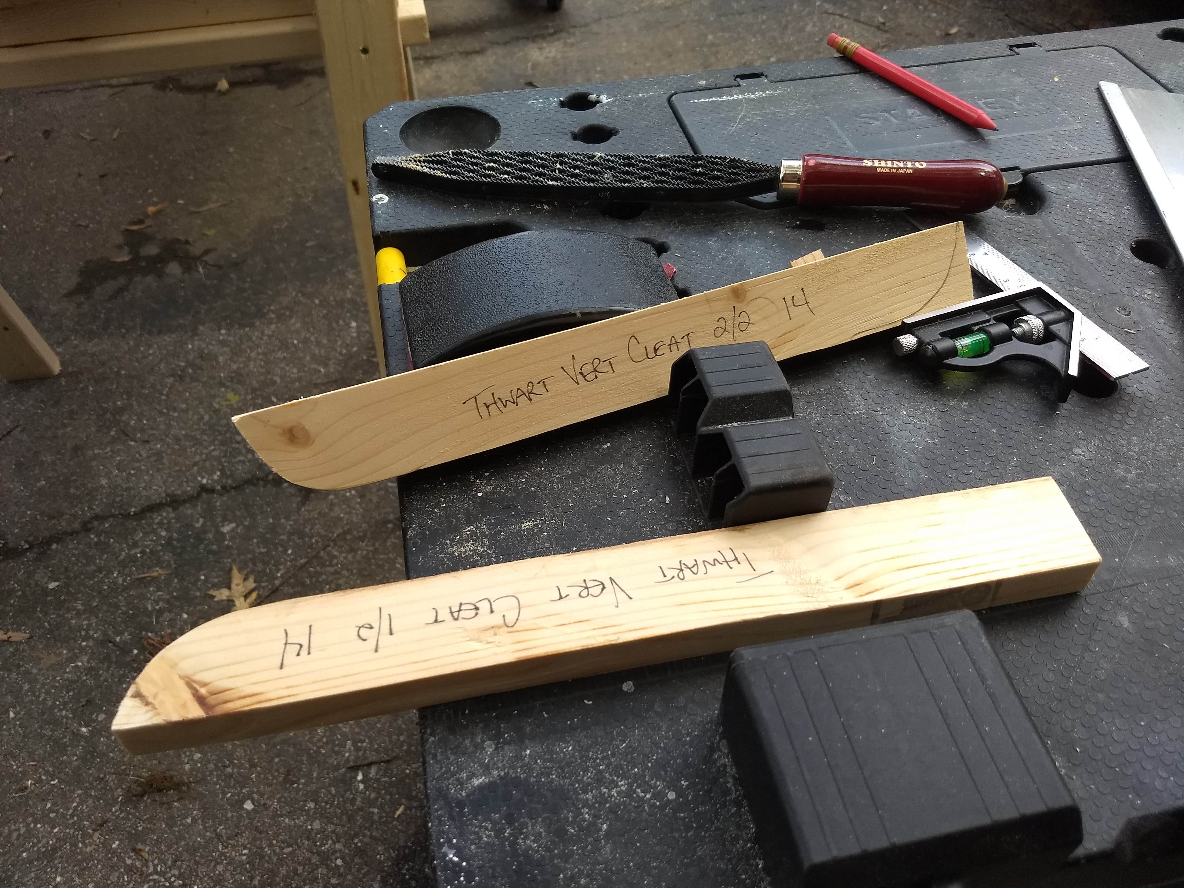
After having dry fitted the cleats last week, I started worrying that just gluing and screwing them to the frame and support wasn’t going to be strong enough. So this week I decided to lap the joints a little bit, chiseling into the verticals to fit the horizontals into slots.
Starboard support in notch
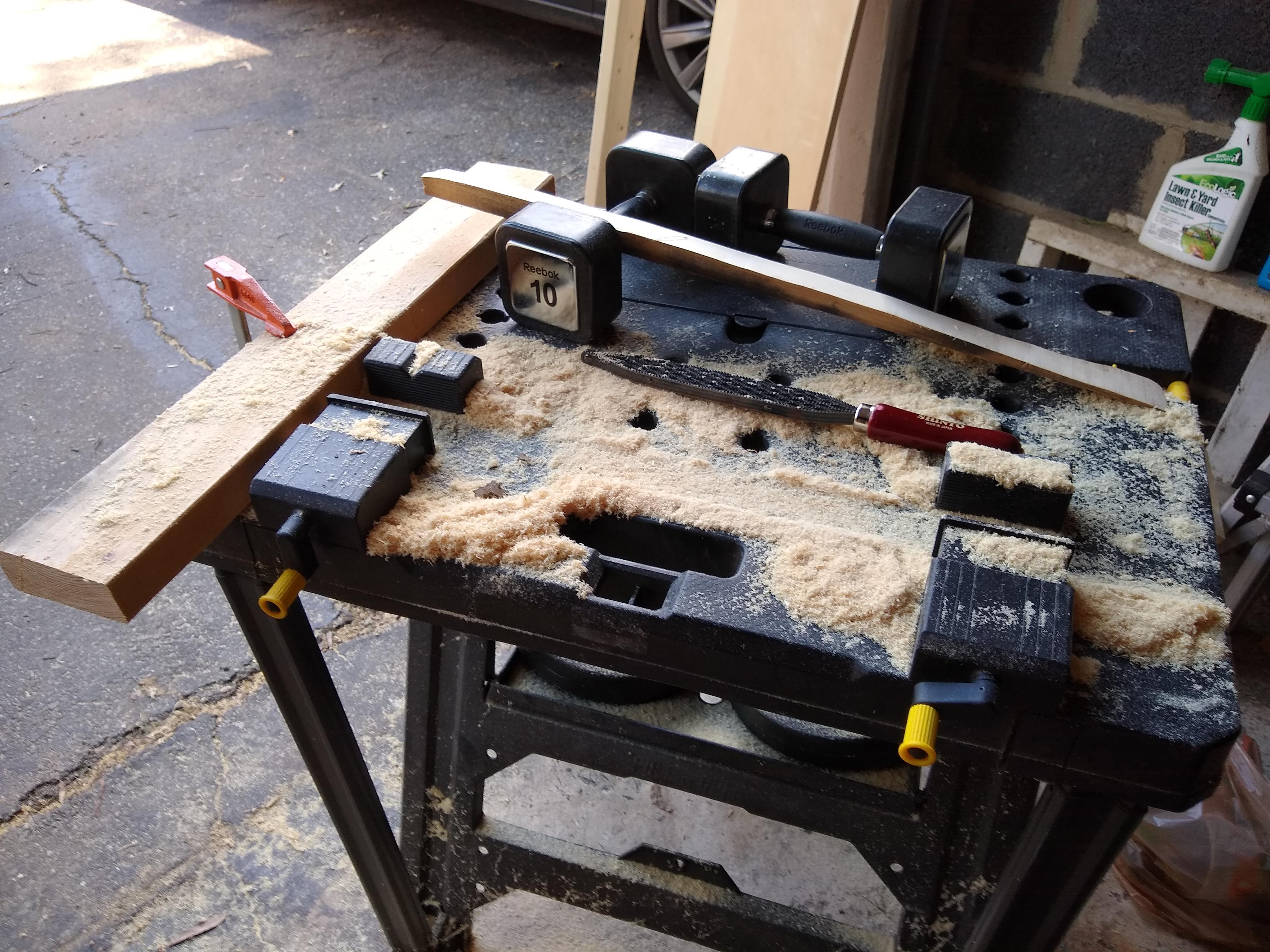
I sharpened the beater chisel a little and, using that and a mallet as well as the rasp and some 100 grit sandpaper on the block, was able to make some nifty slots for the horizontals to sit into.
Port support in notch
I was really rather pleased with the ease of it all and the resulting mechanical strength, which I then permanently added the glue and screws. I think they’re pretty solid now.
Tub o’ DAP ready to go
Then I went about filling all the many screw head holes, from attaching the inwales and the keel, with wood filler. I’d had to buy yet another tub of the DAP filler, having used the last tub and a separate tube already, not to mention a can of the Minwax 2-part filler.
Inwale holes filled
The DAP stuff isn’t the easiest stuff to work with, I find. I wish I knew what I could thin it with, just a little maybe, to make it flow a little better. Although, I suppose I’m filling lots of holes on vertical surfaces. Better to be a bit too thick than too thin, I guess.
Keel holes filled
I put it all on rather rough, trying to get it all done with the tub open, wasting some probably, but I’d be wasting some more even if I let the tub dry out while I had it open.
Breast hook slathered
Should be ready to sand, and maybe need some touch up, next weekend. Then it’s on to final sanding and painting.
Slowed way, way down on progress what with our exchange student coming to live with us. Missed a weekend getting ready for her to arrive, and then another weekend when she did arrive. (And, okay, fine, I missed a weekend before that because I went actual sailing.)
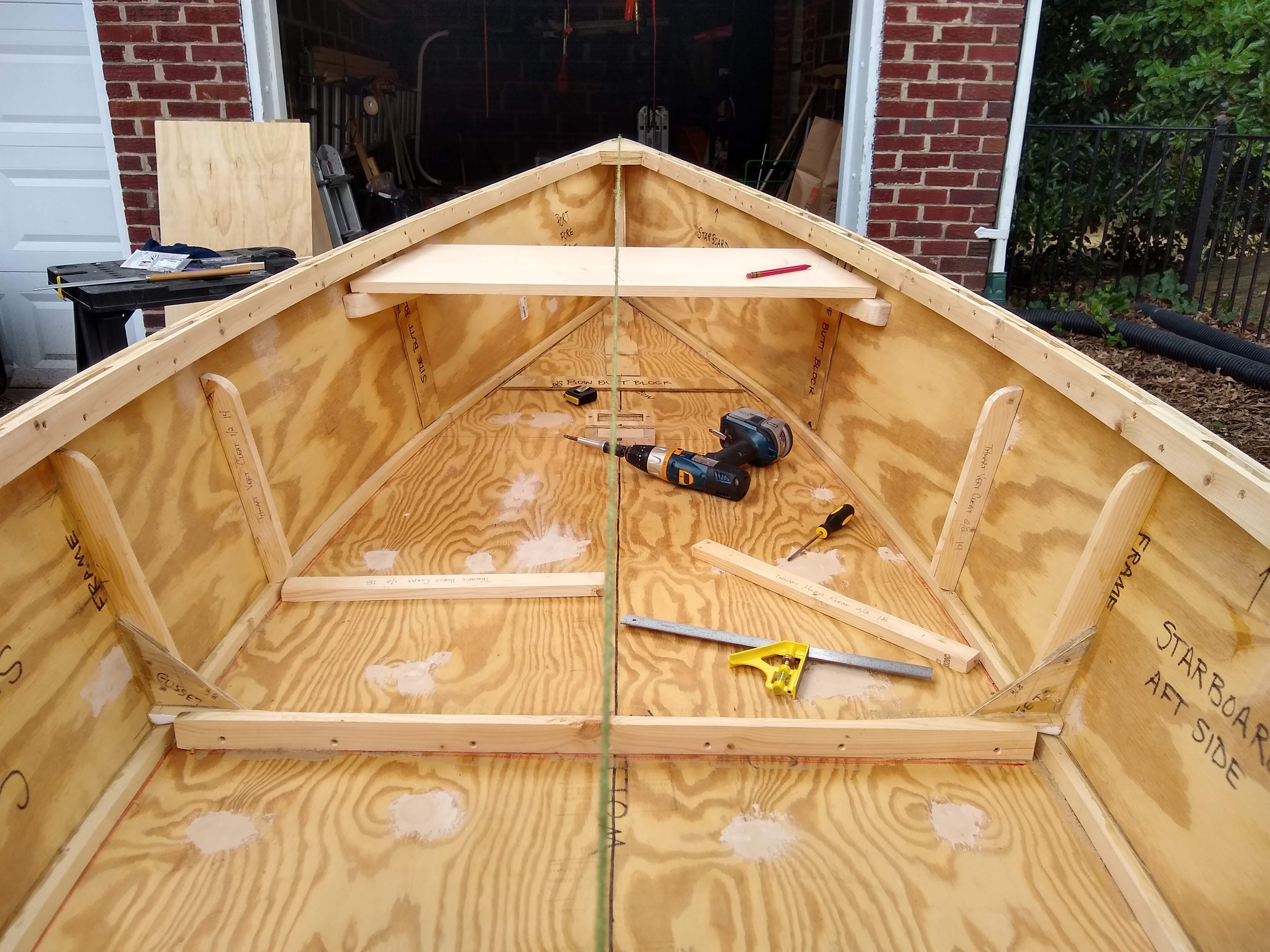
Thwart support cleats screwed into place
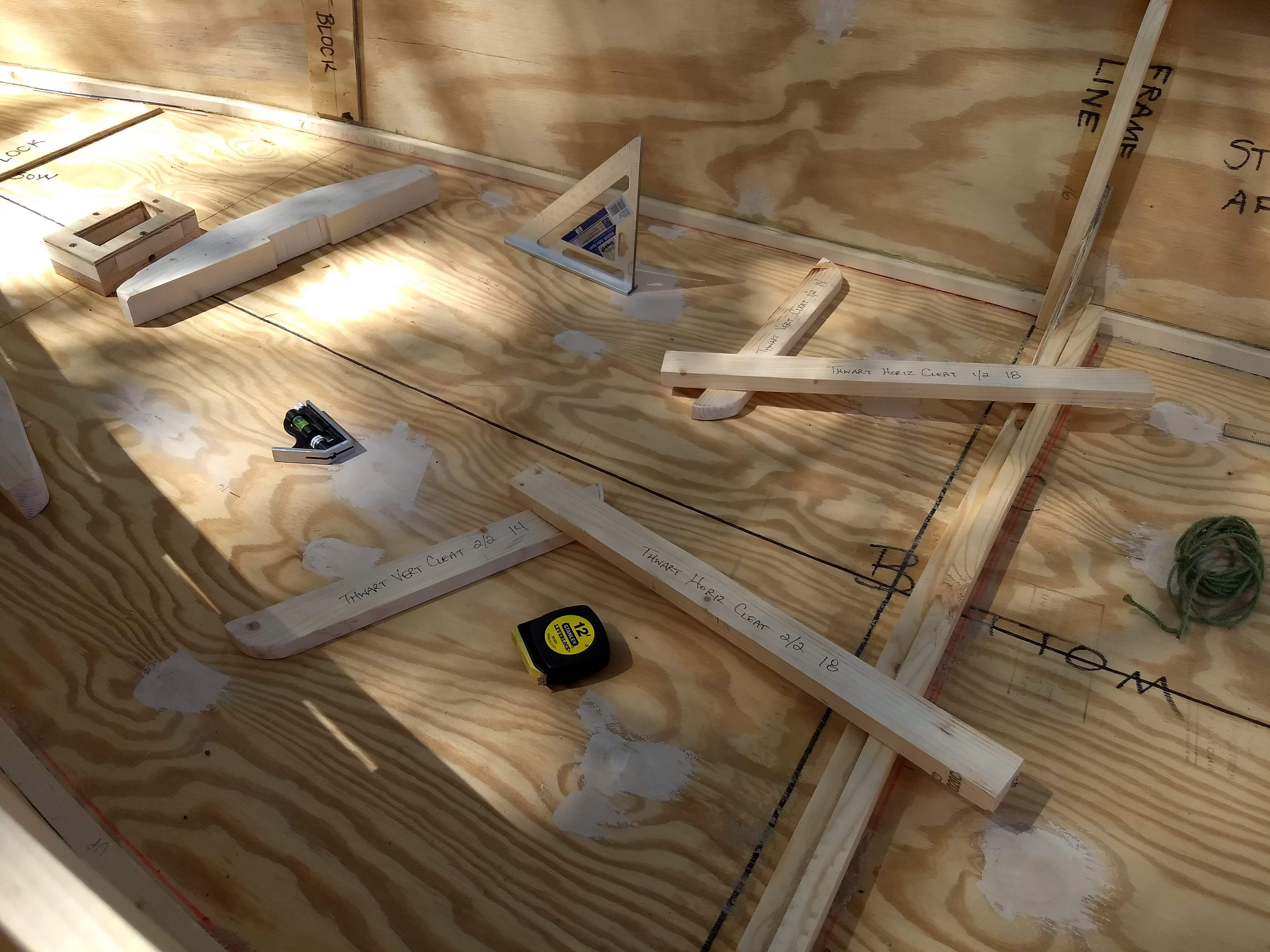
And, even then, the progress that I made this weekend was rather minor. I made some final decisions as to height and placement of the horizontal cleats that will support the thwart and so dry fitted those in place.
Imagining that 2×4 is a thwart
And I finally tackled the poor shape of the furniture dolly that I use to move the boat into and out of the garage. The terribly cheap cloth that covered it was ripping in spots, and I was worried that one of these days the board underneath was going to gouge the transom.
Fraying cloth
So I painstakingly ripped off the cloth, dusty and falling apart, although most of the staples attaching it originally wouldn’t come out. I recover-ed it with cut up pieces of a $3 rubber-backed door mat that I’d bought at Home Depot.
New cloth …
It really came out looking rather snazzy, I think. Protects the boat a whole lot better for sure.
The last major attaching of parts is complete. This boat is almost ready to be painted.
I mentioned last week that I’d erroneously filled the countersink holes for the screws holding the thwart vertical cleats and, hence, had dug the wood fill out. I’ve decided that I want to move those vertical cleats closer to the frame verticals, to shorten the space between the thwart horizontal cleat holders. I had long planned to have the space between like 9″ or so, but when I used the mast partner as a thwart substitute to site the vertical cleats, I used the entire width, making the verticals about 12″ apart.
So this week I corrected that distance, making it the 9″. I’m planning to notch the thwart, to make it reversible, to maybe be able to accommodate rowers of different heights? Maybe? I don’t know. It was an idea anyway.
Moving the cleat closer to the frame
I also mixed up one more batch of epoxy and cut a couple squares of fiberglass tape to fill in a few small areas, one where the stem meets the bottom and another at the starboard side where the transom meets the bottom, where I didn’t feel like I quite got enough coverage last week.
I also cut the slot in the upper lee board guard, which did not go as well as I would have wanted. It was easy enough to drill holes on either side of the slot, per the layout lines on the underside, but the jig saw blade apparently deflected rather seriously when I sawed out the area between the holes. The kerf lines met in the middle on the underside (which was the top side as I was sawing), but they weren’t especially close when I turned the guard right side up.
Drilling for the lee board upper guard slot
So I chopped out the middle apart and used the trusty old rasp once again to even out the deflection. It makes the slot a little wider than I had originally planned, but I think it’s going to be okay.
Lee board guards complete
And with that, with the thwart vertical cleats, the mast partner knees, and the upper and lower lee board guards all done, I was ready to glue and screw them in place to permanently attach them. Which I did, and which was easy and pleasant work. And that just left the keel and skeg.
Drilling pilot holes for the keel and skeg
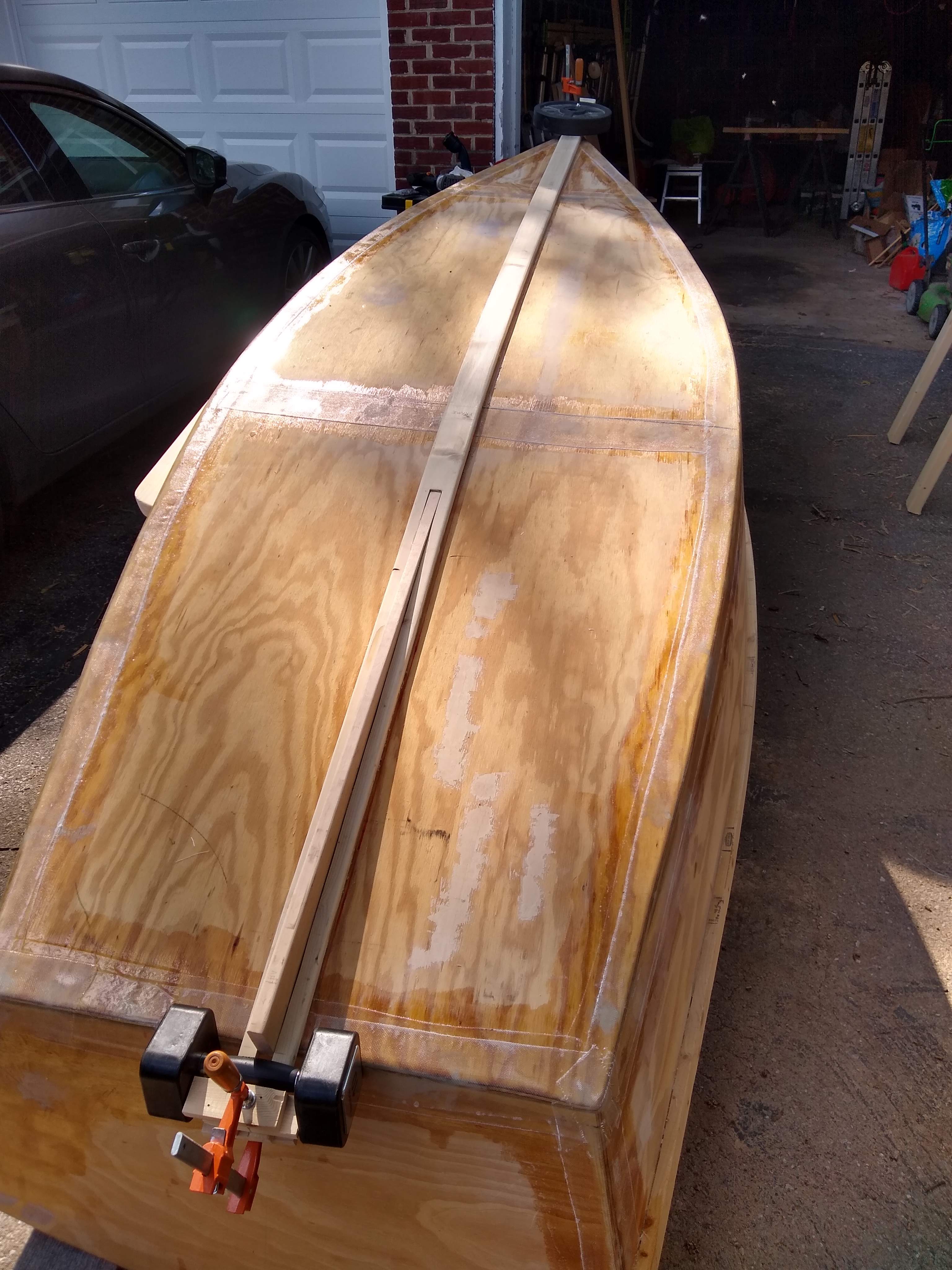
Which the keel and the skeg turned out to be really taxing to attach. It was similar to attaching the bottom, where I had to do it in two quick installments, this time because the keel piece was rather springy and didn’t want to lay down flat all along the boat without a lot of weight on it. So I spread glue along the forward two-thirds or so and weighted down the front half first. I had drilled pilot holes from the outside to the inside every six inches, so underneath I just had to find each pilot hole, drill with the #6 screw countersink back through into the keel, and then screw in a 3/4″ #6 screw. Then pretty much same for the back of the boat. Slather on the glue (although the tube I was using ran out, so I had to reload the gun), then crawl underneath and start drilling and screwing.
Sweaty … filthy …
It wasn’t quite that easy, though, since I was working underneath the upside down boat, sitting on the ground, having to drill and screw with the heavy 18V cordless driver over my head. The driver got heavier and heavier, it seemed, and my whole right arm was shaking and exhausted, by the time I finished the front half. I was bathed in sweat, and filthy, by the time I finished the back half.
… exhausting work.
But it was done. The keel and skeg are on the boat.
Keel and skeg attached. I left the weights on while the adhesive cures.
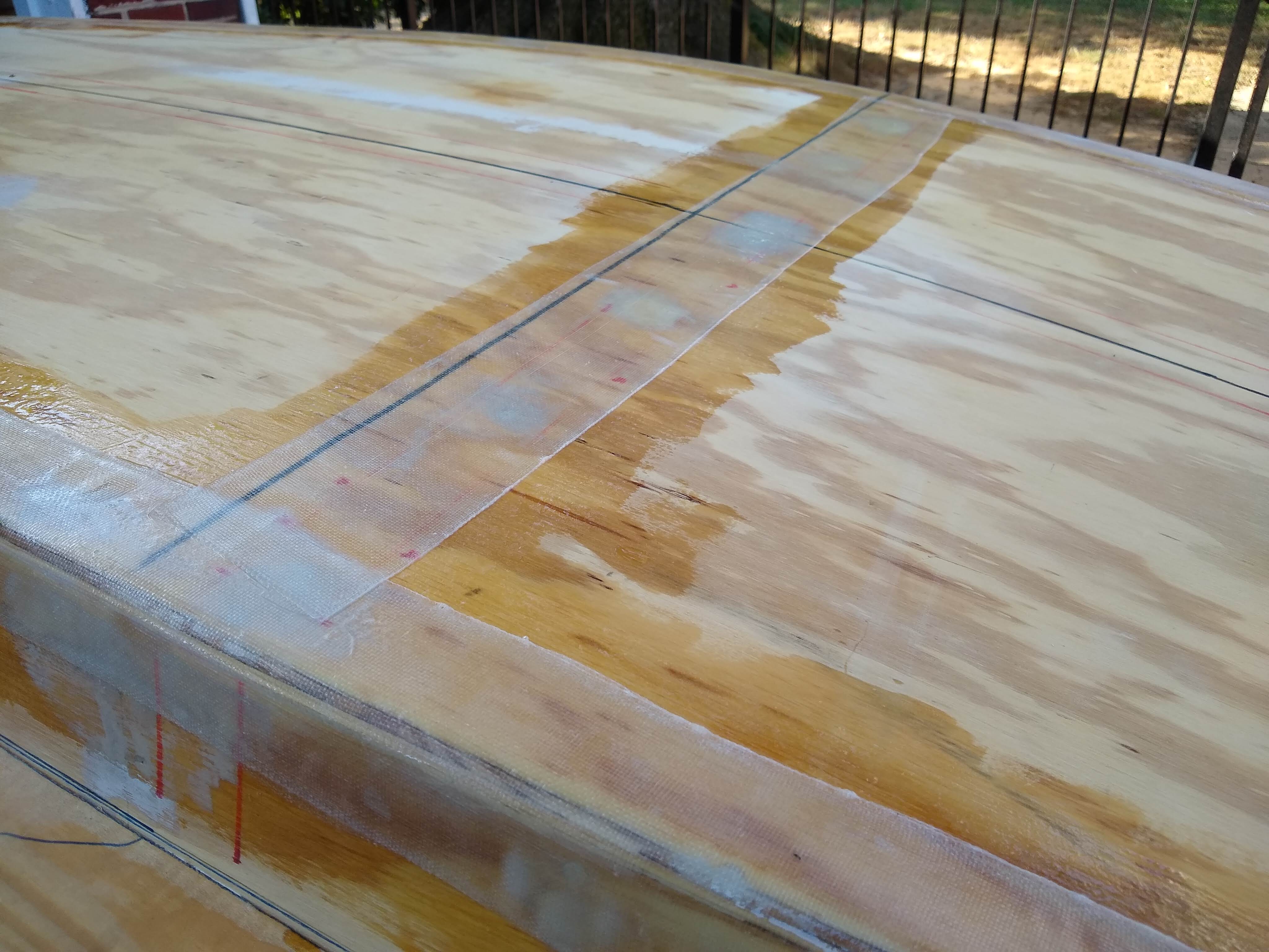
The chines are glassed! At long last, the chines are glassed!
1 quart Raka 127 resin, 1 pint 350 non-blush hardener, 45 meters of 4″ 6 oz standard woven tape
Perhaps the biggest step since Week 29 when the work became an actual boat, sealing the joined plywood with fiberglass and epoxy was quite the milestone. I hadn’t actually planned on glassing anything on the boat when I first started planning. But having come this far, having put this much work into it, much more and much harder work than I thought it would be, I want to maximize the seaworthy-ness of this boat.
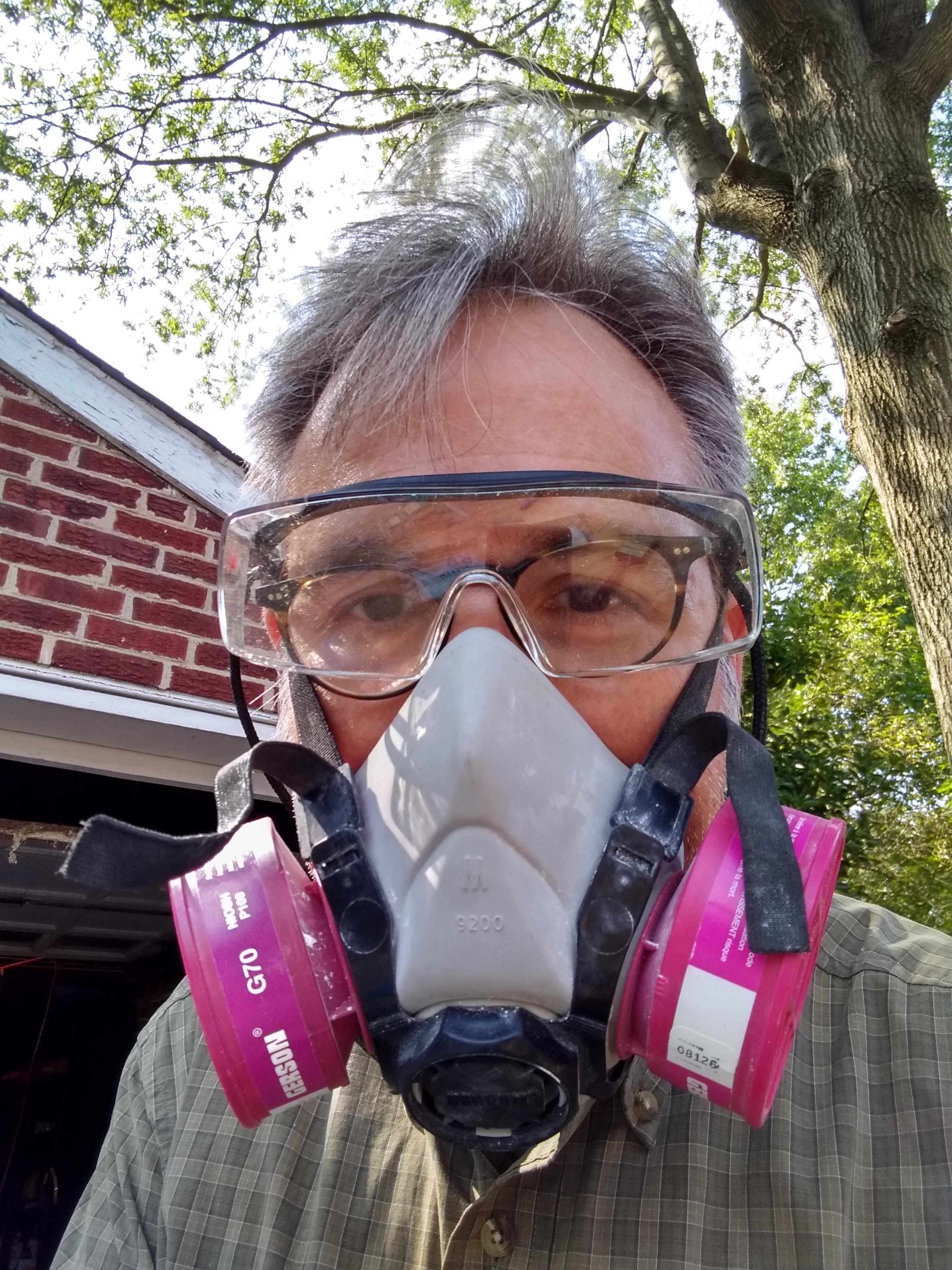
Safety goggles and respirator. Not shown: lots and lots of nitrile gloves
And it was a big learning step as well, given that I’ve never worked with fiberglass and epoxy before. But everbody’s gotta start somewhere, I guess. The biggest help was the manual that Raka has on their website. Great products and great advice!
Measuring tape lengths
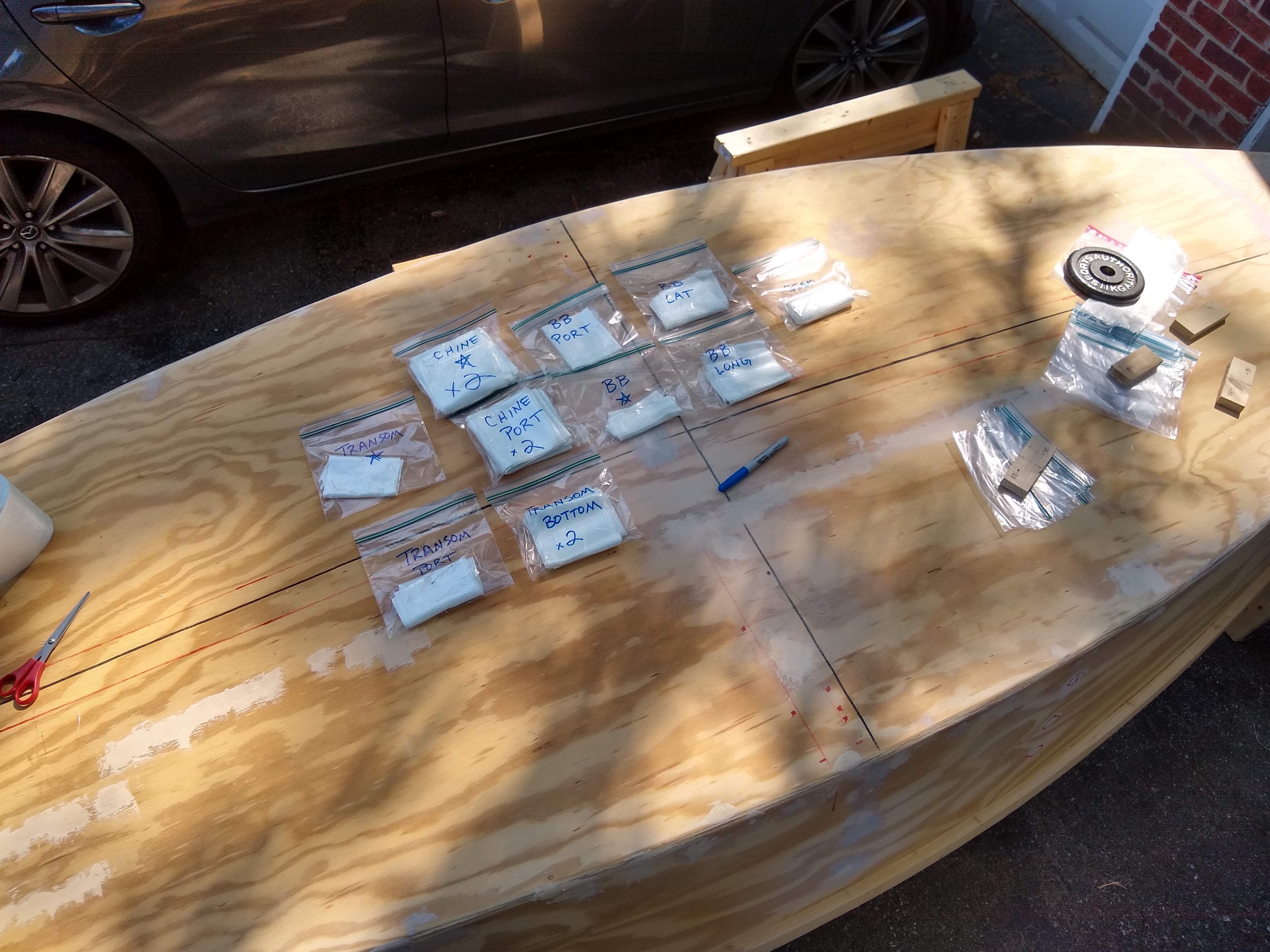
I pre-measured and cut all the tape lengths before mixing any batches of epoxy, putting the lengths in labelled sandwich bags. I used plastic cups marked at an inch or so high line to make sure I was getting the right ratios of resin and hardener. I stirred the batches together for a count of 60 in a 1-quart mini bucket before pouring each batch into a wide flat tray (from Chinese takeout) to keep the batch cooler than it would be in the mixing pot.
Labelled tape lengths
I painted on a base coat of epoxy on each chine or seam with a 3″ paint brush, then laid the length of tape in place and coated over again with a little 3″ trim paint roller. Each batch lasted for the better part of half an hour, and I was able to finish the whole boat in four batches. Judging by the amount left of resin and hardener, I was using about 5 oz. of resin (and half that of hardener) per batch.
Port chine and bottom frame cover
It was exciting, nerve-wracking work. But it’s gonna be so good for the boat.
Finished for the day, so back in the garage while it cures
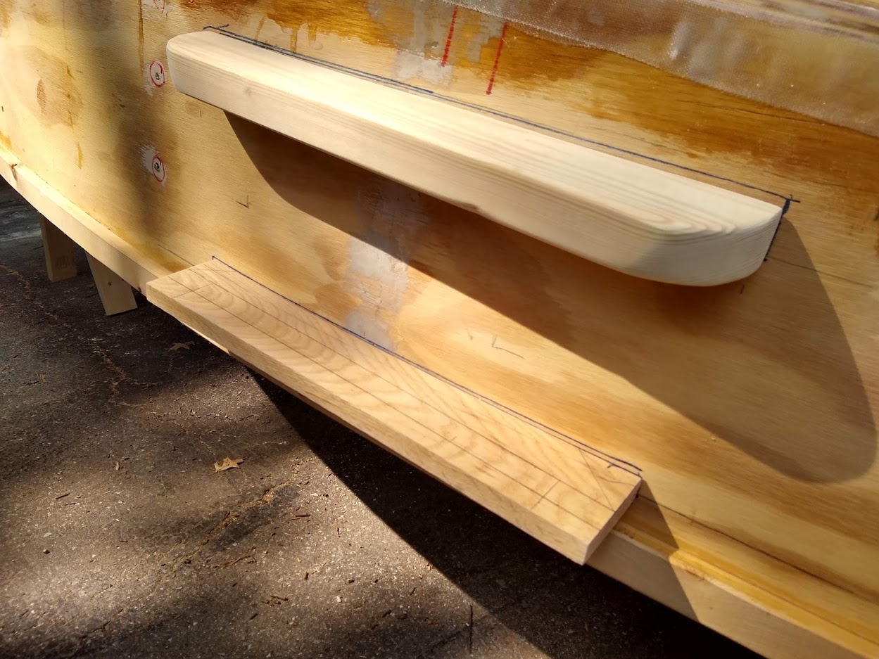
On Sunday I worked a little to shape the lower lee board guard, with saw and rasp, to round the ends, which I imagine helps to transfer the load to the hull more evenly, and it looks better to boot. I had planned to cut the slot in the upper guard today, but I didn’t quite have time for that.
Lower guard shaped. The boat is upside down here, is why the lower guard is above the upper guard.
I also dug out the screws going from the outer hull into the vertical thwart supports, which screw holes I had filled last week as I was filling the last of the holes to be covered by the glass tape. I mistakenly also filled these thwart support holes, when I hadn’t actually glued the supports to the inside of the hull.
Next week is finishing the upper guard and attaching it and all the other finished parts, including the keel, now that the chines and seams are glassed.
Dawn went out of town for a weekend and I found myself too busy on the one hand and rather unmotivated on the other, so I skipped a weekend of boat building. The following weekend was dangerously hot, but I couldn’t miss a second weekend. So I worked out in the brutal heat. And I dry-fitted the mast partner knees and lee board guards.
I did purchase a few more pieces of wood last weekend, despite not actually working on the boat.
In order to fit the mast partner board to size, I needed to screw on the mast partner knees. I would’ve just gone ahead and glued them on as well, but I figured it was too hot for gluing. Plus I’ll just go ahead and glue on the keel, skeg, mast partner knees, thwart supports, and lee board guards all in one day to maximize a tube of glue. (Although, now that I think about it, I’ll probably glue all the parts while the boat is right side up before I turn it upside down and glue on the keel and skeg.) It was only when I was screwing them on that I realized that I’d made the knees symmetric over the butt blocks rather than over the 50″ line for the center of the mast partner. It’s not a huge mistake, but it bugged me. Not enough to try to make those parts again, though.
Mast partner layout
I laid the mast partner board across the boat and fiddled a lot with centering and aligning it. Eventually I stretched a string along the length to better keep track of the center line. And I made sure I centered the mast partner across the boat at the 50″ line rather than the butt blocks. It makes them sit a bit aft on the knees, not too far I think to affect performance. But it still kinda bugs me that I made the knees off-center.
Mast partner centering
It took a couple of cuts on each side with the jig saw, as I was trying to keep the mast partner as long across as possible, to be able to just fit under the inwales. I finally got it to my liking. And, while I was at it, I used the mast partner board as a template for the thwart, to be able to place the thwart vertical cleats and dry fit them into place.
Mast partner fitted and thwart vertical cleats fitted
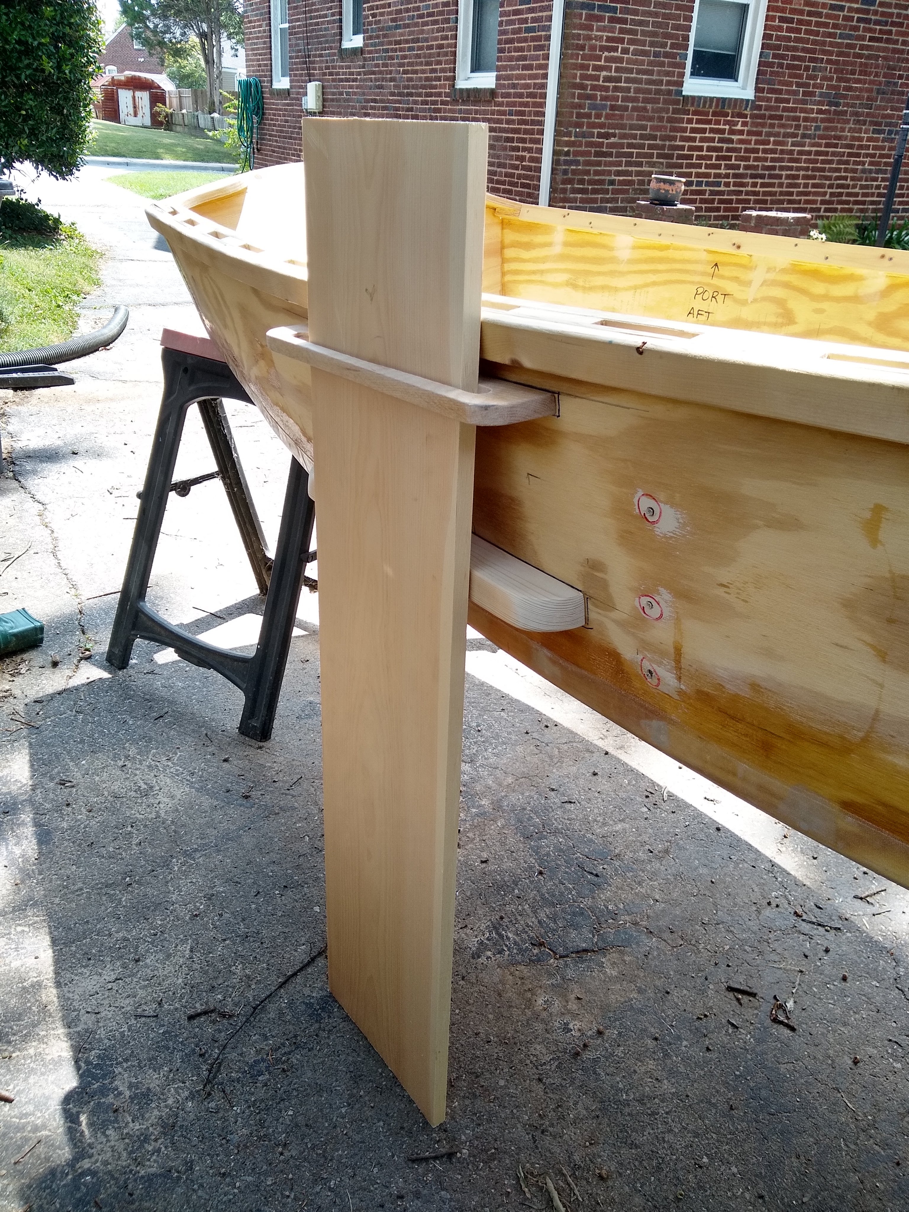
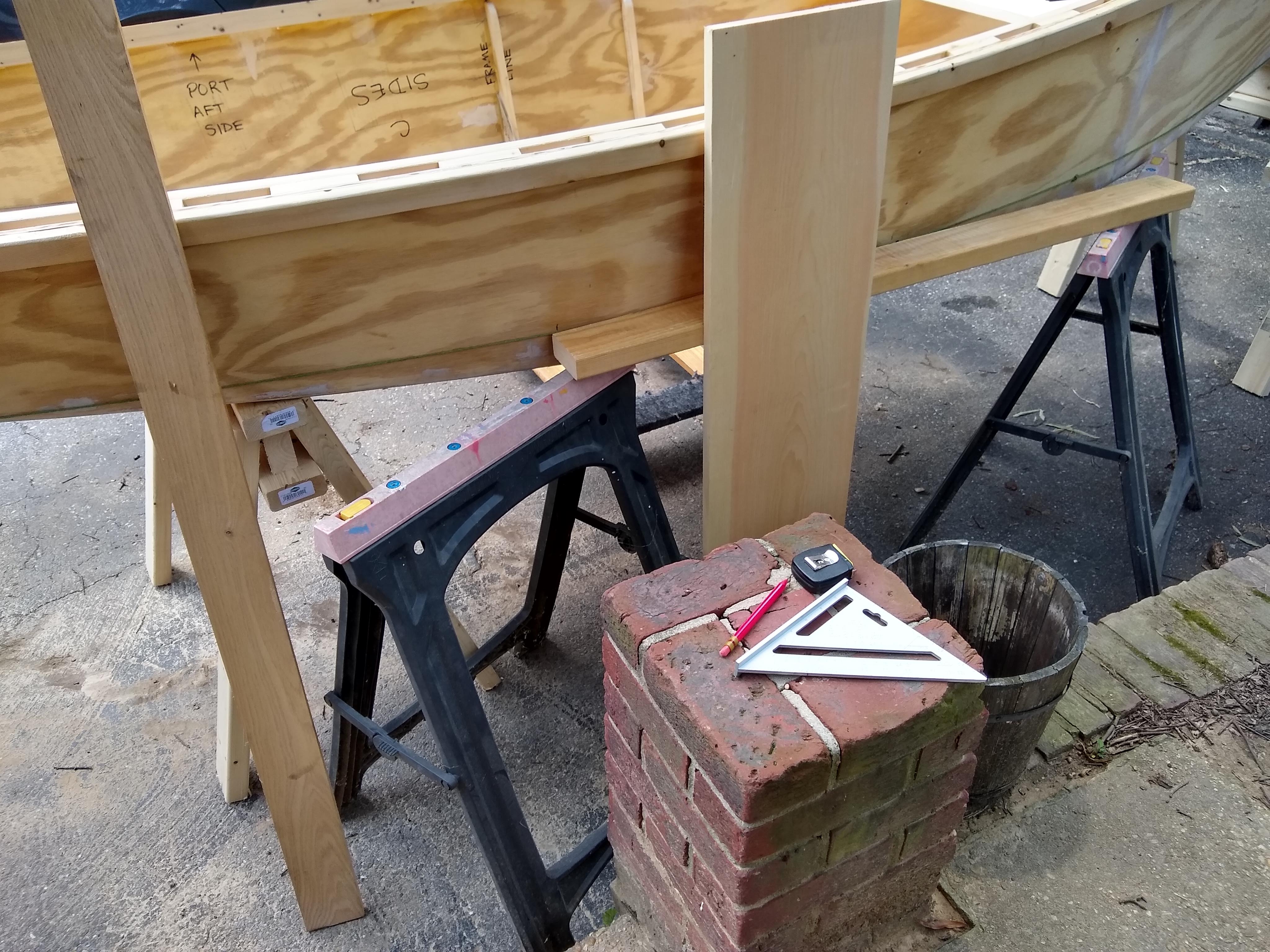
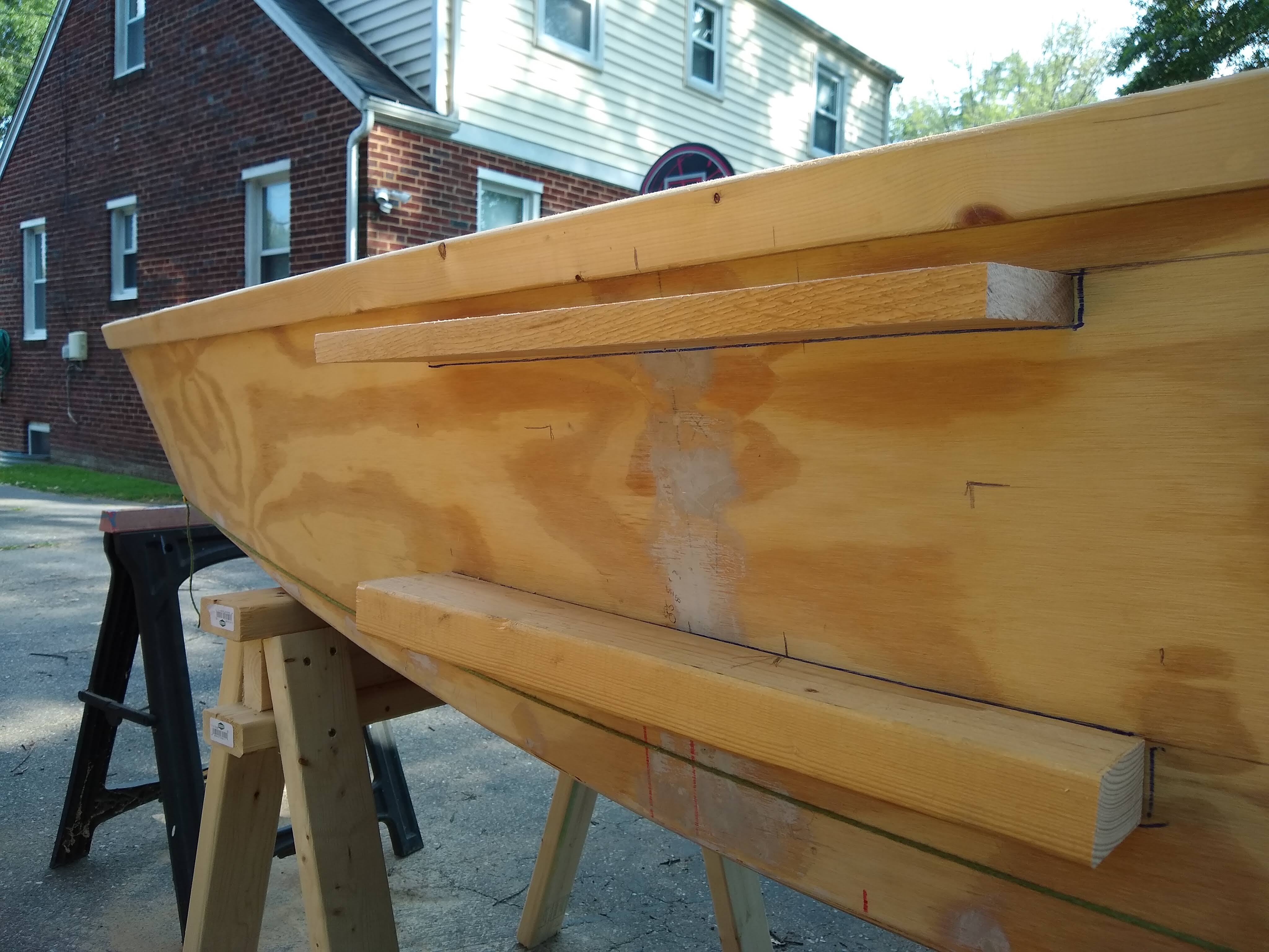
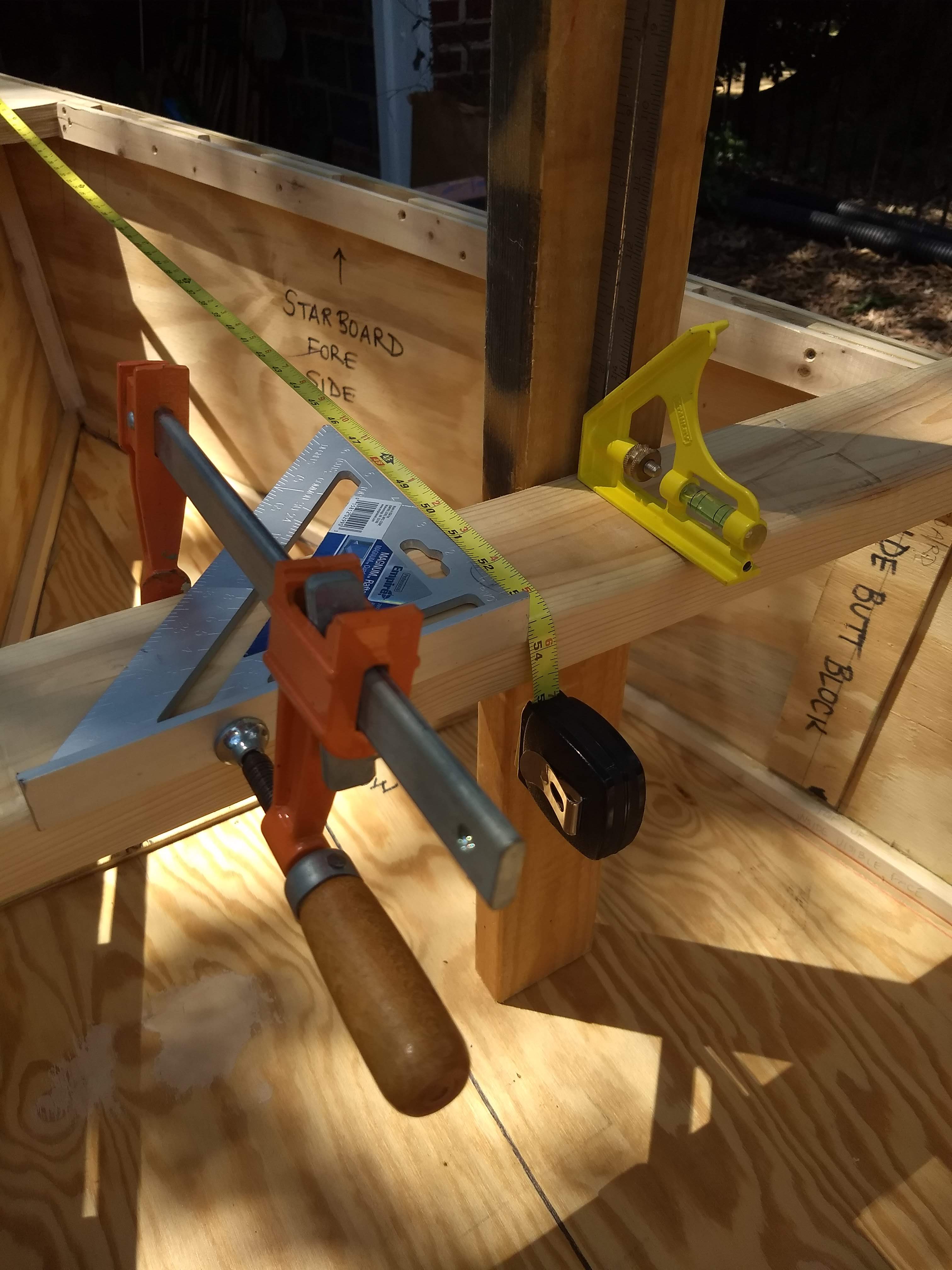
On Sunday I tackled the supports for the lee board. The lee board needs to pivot on a lower guard while also held in place by an upper guard. I haven’t been able to calculate very well the placement of these two parts, either on paper or on the computer, so I just started measuring and marking and cutting on the boat itself. Bespoke parts!
Lee board and guard measuring
I used a string to approximate the water line as best I could, assuming the water line to be the line between the bottom of the stem and the bottom of the transom. I think that’s right. Then I wanted the lower guard to be just above the water line, wanting as much space between the upper and lower guards, per Jim Michalak’s advice:
The farther apart they are spaced, the more effective they are at sharing the loads of the leeboard. If the guards get quite close together, they probably won’t always be strong enough and having the leeboard break loose will ruin your day.
Jim Michalak
Rasping and more rasping
Just like the mast partner knees, it was quite a chore fitting both (1) the curve of the boat fore & aft and (2) the flare of the hull up and down. Again I rough cut the curve and angle with the jig saw and then went at it with the rasp until it fit about as well as I could get it. It was hard but fun, and it produced a lot of fine shavings.
Lee board guards fitted
Next step is to cut a slot in the upper guard to brace the lee board in both directions. The lee board will be bolted to, and pivot on, the lower guard.
Working three days of a four day weekend, I finished making the keel and skeg, the mast partner knees, and the thwart vertical supports. I also measured the boat to determine the placement of the lee board. I had hoped to glass the chines, but, sadly, the epoxy that I’d ordered did not arrive yet.
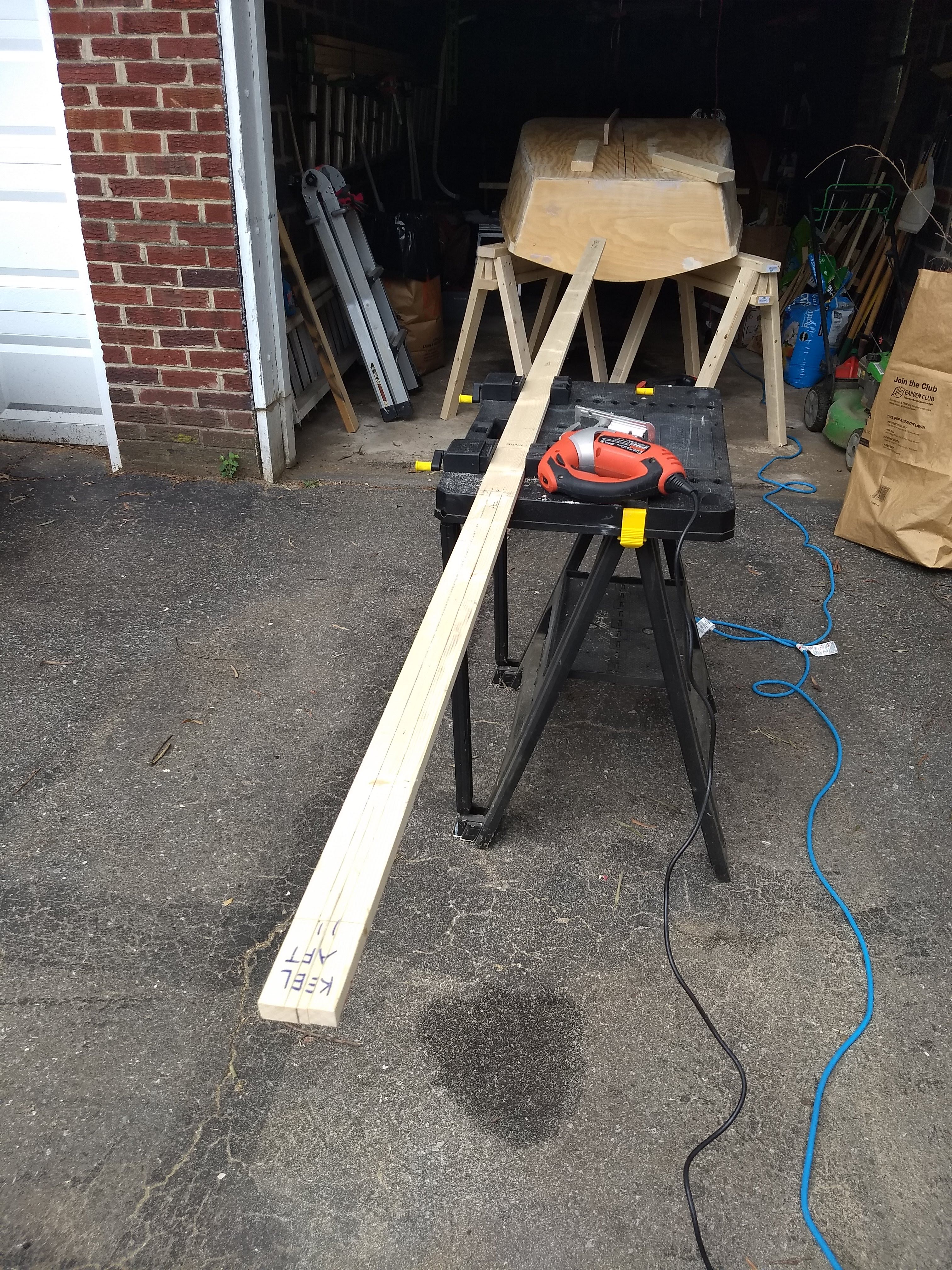
Last week I’d traced the outline of the skeg onto the keel board, so this week, on Thursday July 4, I cut out the slot. I was worried about how to cut straight on such a long piece, alternating between thinking of using the table saw, compact circular saw, or the jig saw. In the end I went with the jig saw. It’s slower than the compact circular saw, but with that slowness comes a bit more accuracy cutting to a particular line. Plus, the circular saw doesn’t cut straight up and down, duh, since it’s a circular saw, and the end of the cut into the keel, where the cut stops in the middle of the keel, that end needs to be a straight block to house the 3/4″ tall end of the skeg. So, jigsaw it was.
Ready to cut keel slot
The jig saw was also able to curve from one side of the slot to the other, to remove most of the waste at the slot end, whereupon I used a 3/4″ wide chisel to straighten the slot end. I was in a hurry and used the junk chisel, where I really should have gone back into the basement workshop and found a better chisel. But the end slot is eventually getting filled with the skeg and the PL Premium polyurethane adhesive and either caulk sealant or epoxy & filler if I’ve got epoxy left over after glassing the chines. And then it’s going to get 3 coats of paint. A little rough chiseling isn’t going to make a huge difference in performance or appearance.
Keel slot cut and chiseled
I also softened the hard edges of the keel and skeg. I would have rounded them over with a router if I’d had a 3/8″ roundover bit, but, alas, I only had a 1/4″ bit and couldn’t find a 3/8″ bit at Home Depot. Instead I just used the rasp and a block with 100 grit sandpaper. I don’t imagine that makes much difference, certainly not in performance, except maybe they’ll be less susceptible to dings after being painted, or appearance, although I think it looks a little nicer.
Softened edges on skeg and keel
On Saturday I worked a little on the interior of the boat, making what I’m calling the knees for the mast partner. I’m deviating a little from designer David Beede’s quite unequivocal advice: “The mast partner should not be removable but fastened securely to cleats as a lot of torque is transmitted to the hull through this piece.” Somewhere in my reading I came across an article about adding a balanced lug rig to Cheasapeake Light Craft’s Northeaster Dory, where there’s a “mast thwart assembly” that I’m trying to copy instead. CLC uses cleats that are 1″ thick, 3″ wide, and 13-1/2″ long. My plan for a knee, starting with a length of 2×4, was to be 1-1/2″ thick, 3-1/2″ wide, and 15″ long.
It was awfully difficult, though, cutting these pieces to fit, owing to (1) the curvature of the boat from fore to aft and (2) the flare of the hull up and down. And then, just to add to the difficulty, the knees attach fully across the butt blocks on either side, so I needed to either cut a 1/4″ channel in the middle of the backside of each knee or shim them on either side of the butt blocks. Yikes.
Mast partner knees
I started out doing pretty well, using a smaller scrap of 2×4, to test cutting the curve and flare with the jigsaw. It fitted into place on the starboard side just fine, except for the butt block. So then I used that test piece as a template to cut a full-size length of 2×4, this time using the compact circular saw, but that piece didn’t fit nearly as well. It was terrible. And then neither piece fit well at all in place using 1/4″ ply as shims on either side of the butt blocks. In fact, it just made it worse. This was turning into a disaster.
Port mast partner knee held in place
I was able to cut a second length, this time with the jig saw, that fit fairly well onto the port side, after some rasping and sanding. But, again, the ply shims just made it worse. So I resolved to cut channels to fit the butt blocks. I cut 1/4″ long notches all along the channel areas with the jig saw, using it almost like the dado set on the table saw, until the channels were cut, then I used the good old rasp and sanding block to smooth them out as best I could. Like the chiseled end of the keel slot, these are going to be filled with adhesive and caulk, so they’re not perfectly smooth channels, but they’re close.
Starboard mast partner knee held in place
But since I ended up using my first test piece as the final knee on the starboard side, the knees are not the full 3 ½” wide anymore. They’re more like 2 ½”. But, still, imagine the CLC knees at 1 × 3 × 13.5 making a volume of 40 ½ in3, where my knees at 1.5 × 2.5 × 15 are 56 ¼ in3. (Then again, CLC uses cedar, where I’m using … whatever Home Depot was using for dimensional lumber the week I bought it. Who knows?)
I’m imagining worst case scenario is replacing the bolts and star knobs that I’m planning to use for attaching the mast partner proper to the knees, making it removable for rowing with a passenger, with screws and glue to permanently attach the mast partner and having less room or comfort for said theoretical passenger.
Rounding ends with rasp
On Sunday I tackled the supports for the rowing thwart, at least the vertical ones, where there’ll be one on each side some length afore of the frame. I was a little disappointed to discover, all these many weeks and months after having made the frame, where at the time I softened the edges of these vertical supports, that I wished I hadn’t softened the edges before mounting the horizontal brace cleats atop which the thwart will rest. Those soft edges leave less material to attach the horizontal cleats. Oh, well. Live and learn.
Knees and thwart supports
Mostly today I just rounded the ends of the vertical supports, to better transfer any load on them to the hull as well as just look similar to the rounded ends at the tops of the frame. Only after rounding both the top and bottom ends, though, did I wish that I hadn’t quite rounded the bottom ends, to better let those rest on the internal chines, transferring more load to the bottom of the boat and not just the hull sides. Oh, well, again. Live and learn. I can still notch off those bottom roundings to rest on the chines.
Finding widest point on hull for lee board
Finally, having some time left on Sunday, I measured to find the tangent point along the outside starboard hull, where the center of the lee board should be. I was expecting to find it at 82″ back from the stem, per Beede’s design instructions, but instead I measured it at 85-5/8″ back. I thought maybe I’d made a mistake or that the 2×4 I was using was crooked or something. But I re-measured with string and got the same results. I’m using this measurement to site where the upper and lower guards of the lee board are going to be, so I’m not ready to commit yet to these as a final measurement. Plus I imagine I’ll have some room along the guards to move the lee board fore or aft, depending on the center of effort of the sail, eventually. But I’m puzzled. A little disturbed, even. I’m trying to not let this all upset me too much yet.
I worked in the blazing heat on Saturday filling screw holes and seams on the outside of the boat, and then on Sunday I installed the mast step.
Wood filler work station
I didn’t really mean to work all afternoon on the stifling heat on Saturday. I probably should have waited until it was cooler to work with the two-part Minwax wood filler. But I’m so eager to finish the boat that I didn’t want to waste a weekend. So I slogged through. And, really, it was in the low 80s in the garage. I don’t imagine it getting cooler enough in the coming weeks to bring that temperature in the garage down much more.
Bow butt seams getting filled
The main problem became the working time for the filler once I got it mixed. Minwax claims that there’s ten to fifteen minutes after mixing at room temperature. In the hotter garage I got maybe five if I was lucky. So mostly I just mixed smaller batches at a time, just enough for five minutes of work. I used the kitchen scale, measuring in grams, although it measures in whole grams and I wished I had a scale at tenths of a gram.
Working on the upside down boat, scraping and sanding wood filler
The recommended mix of resin to hardener is 16 to 1, so I was trying to mix 16 grams of resin at a time to which to add 1 gram of hardener. Usually it was a blob of about 20 grams or so, and I soon got a feeling for how big a dab of hardener to add to that. Only once did I apparently add too much hardener and end up with an unusable rock on my taping knife/palette/mortar board.
See any unfilled screw holes?
I used up the whole can of resin, so I must have done somewhere between fifteen and twenty batches, over the course of two to three hours. I was sure glad when it was done.
This spot had the worst gouge from trimming the bottom flush weeks ago. It filled in nicely.
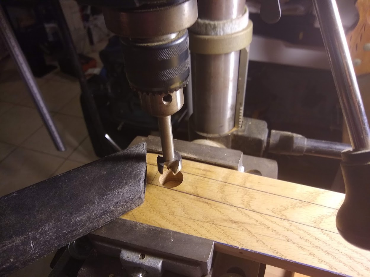
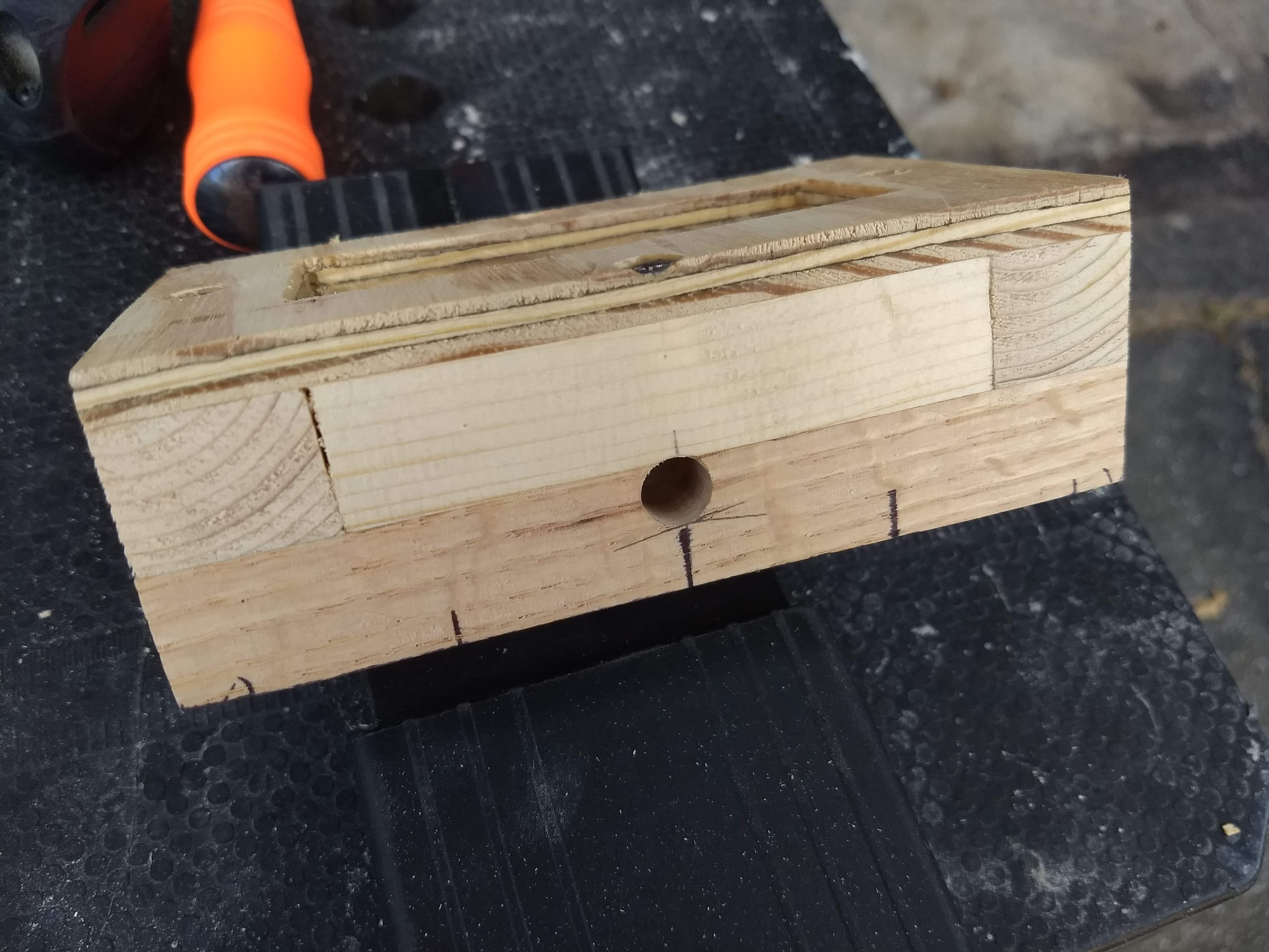
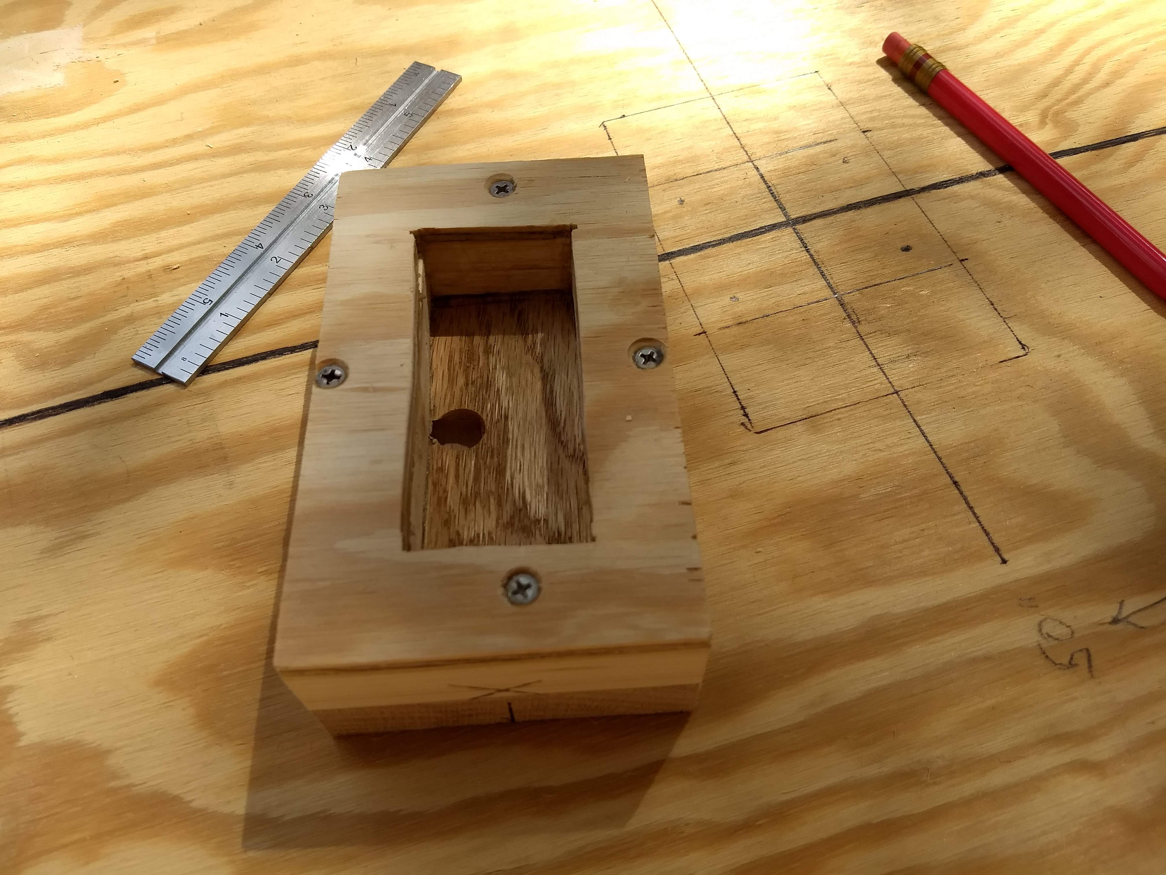
On Sunday I worked more on the mast step. I unclamped it and took it down to the basement workshop to even up the sides on the miter saw. Then I drilled a 3/8″ hole through the side at the top edge of the bottom oak layer, and then a 5/8″ hole down into that hole, on the drill press using Forstner bits.
Mast step side hole
These holes will allow any water dripping down the mast into the step to drain into the boat itself. I don’t imagine I’m going to be sailing fast enough or heeled over enough to generate spray that’ll hit the mast. But, hey, you never know.
Mast step inner hole
I took the mast step back outside and installed it. I measured back from the bow the 50″ per the design and traced the step on the bottom hull. Then I drilled four pilot holes. I slathered wood glue on the bottom of the step and in the traced box on the hull bottom, then I put the step in place and held it down with a couple of ten-pound dumbbells. Finally, I drilled and countersunk from below the boat through the four pilot holes, cinching in 4 screws to act as clamps while the glue dried. These screw holes will be later filled with wood filler and then covered by the keel.
Measuring 50″ back for the mast step
Next week I hope to glass the chines and seams, if the epoxy and fiberglass tape that I ordered arrive in time. Then I can install the keel and skeg.